30GN040-420 specifications
The Carrier 30GN040-420 is a well-regarded model within the industry of chillers, designed to deliver efficient cooling solutions for a variety of commercial applications. Its compact design and advanced technology make it an ideal choice for businesses looking to optimize their HVAC systems.One of the standout features of the Carrier 30GN series is its flexibility. This chiller model is available in a range of capacities, specifically from 40 to 420 tons, allowing for customized solutions based on specific cooling demands. Such versatility enables this unit to cater to a broad array of installations, from small commercial spaces to larger industrial facilities.
The Carrier 30GN040-420 utilizes a scroll compressor design, known for its reliability and efficiency. The scroll technology allows for a reduction in the number of moving parts, resulting in lower maintenance costs and increased durability. Additionally, the unit operates with environmentally friendly refrigerants such as R-410A, promoting sustainability without compromising performance.
Energy efficiency is another significant aspect of this model. The 30GN series is designed to provide high energy efficiency ratios (EER), which translates to lower operational costs for users over the lifespan of the unit. This is particularly beneficial in an era where energy costs are consistently rising.
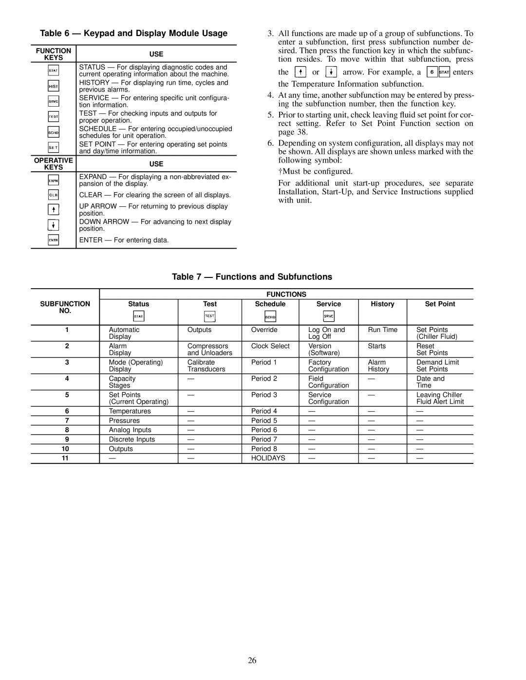
The advanced controls found within the Carrier 30GN040-420 further enhance its performance and ease of use. The unit is equipped with a microprocessor-based control system that allows for precise temperature management while providing valuable diagnostic information. This feature not only improves the overall reliability of the system but also facilitates proactive maintenance, reducing the risk of unscheduled downtime.
Moreover, the design of the Carrier 30GN040-420 emphasizes quiet operation, making it suitable for environments where noise levels must be minimized. This characteristic is critical for applications in hospitals, schools, or office buildings, where a peaceful atmosphere is essential.
In summary, the Carrier 30GN040-420 chiller provides a robust solution for businesses requiring dependable and efficient cooling. Its features, including flexible capacity options, reliable scroll compressors, energy-efficient performance, advanced controls, and quiet operation, position it as a top choice for various commercial and industrial applications. As technology continues to evolve, models such as the 30GN series remain at the forefront, meeting the demands of modern HVAC needs while ensuring sustainability and efficiency.

