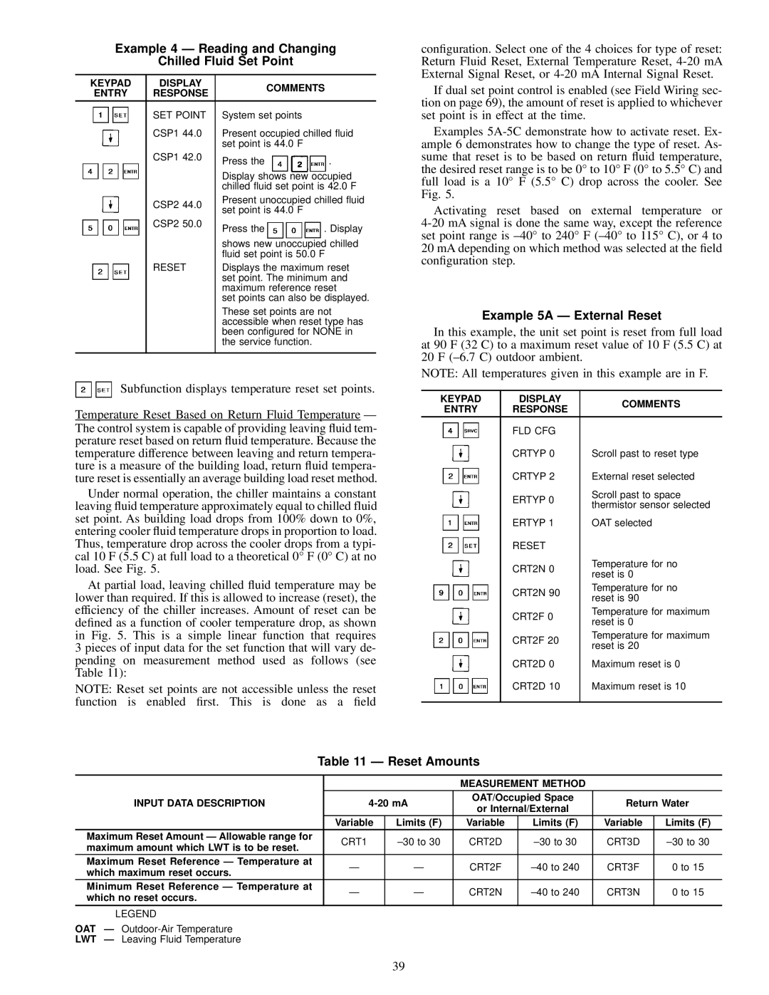
Example 4 Ð Reading and Changing

Chilled Fluid Set Point

KEYPAD

DISPLAY

COMMENTS

ENTRY

RESPONSE


SET POINT

System set points


CSP1 44.0

Present occupied chilled ¯uid


set point is 44.0 F


CSP1 42.0

Press the

.


Display shows new occupied


chilled ¯uid set point is 42.0 F


CSP2 44.0

Present unoccupied chilled ¯uid


set point is 44.0 F


CSP2 50.0

Press the

. Display


shows new unoccupied chilled


¯uid set point is 50.0 F


RESET

Displays the maximum reset


set point. The minimum and


maximum reference reset


set points can also be displayed.


These set points are not


accessible when reset type has


been con®gured for NONE in


the service function.


Subfunction displays temperature reset set points.

Temperature Reset Based on Return Fluid Temperature Ð The control system is capable of providing leaving ¯uid tem- perature reset based on return ¯uid temperature. Because the temperature difference between leaving and return tempera- ture is a measure of the building load, return ¯uid tempera- ture reset is essentially an average building load reset method.

Under normal operation, the chiller maintains a constant leaving ¯uid temperature approximately equal to chilled fluid set point. As building load drops from 100% down to 0%, entering cooler ¯uid temperature drops in proportion to load. Thus, temperature drop across the cooler drops from a typi- cal 10 F (5.5 C) at full load to a theoretical 0° F (0° C) at no load. See Fig. 5.

At partial load, leaving chilled ¯uid temperature may be lower than required. If this is allowed to increase (reset), the efficiency of the chiller increases. Amount of reset can be de®ned as a function of cooler temperature drop, as shown in Fig. 5. This is a simple linear function that requires 3 pieces of input data for the set function that will vary de- pending on measurement method used as follows (see Table 11):

NOTE: Reset set points are not accessible unless the reset function is enabled ®rst. This is done as a ®eld

con®guration. Select one of the 4 choices for type of reset: Return Fluid Reset, External Temperature Reset, 4-20 mA External Signal Reset, or 4-20 mA Internal Signal Reset.

If dual set point control is enabled (see Field Wiring sec- tion on page 69), the amount of reset is applied to whichever set point is in effect at the time.

Examples 5A-5C demonstrate how to activate reset. Ex- ample 6 demonstrates how to change the type of reset. As- sume that reset is to be based on return ¯uid temperature, the desired reset range is to be 0° to 10° F (0° to 5.5° C) and full load is a 10° F (5.5° C) drop across the cooler. See Fig. 5.

Activating reset based on external temperature or 4-20 mA signal is done the same way, except the reference set point range is ±40° to 240° F (±40° to 115° C), or 4 to 20 mA depending on which method was selected at the ®eld con®guration step.

Example 5A Ð External Reset

In this example, the unit set point is reset from full load at 90 F (32 C) to a maximum reset value of 10 F (5.5 C) at 20 F (±6.7 C) outdoor ambient.

NOTE: All temperatures given in this example are in F.

KEYPAD

DISPLAY

COMMENTS

ENTRY

RESPONSE


FLD CFG


CRTYP 0

Scroll past to reset type


CRTYP 2

External reset selected


ERTYP 0

Scroll past to space


thermistor sensor selected


ERTYP 1

OAT selected


RESET


CRT2N 0

Temperature for no


reset is 0


CRT2N 90

Temperature for no


reset is 90


CRT2F 0

Temperature for maximum


reset is 0


CRT2F 20

Temperature for maximum


reset is 20


CRT2D 0

Maximum reset is 0


CRT2D 10

Maximum reset is 10


Table 11 Ð Reset Amounts


MEASUREMENT METHOD


INPUT DATA DESCRIPTION

4-20 mA

OAT/Occupied Space

Return Water

or Internal/External


Variable

Limits (F)

Variable

Limits (F)

Variable

Limits (F)

Maximum Reset Amount Ð Allowable range for

CRT1

±30 to 30

CRT2D

±30 to 30

CRT3D

±30 to 30

maximum amount which LWT is to be reset.


Maximum Reset Reference Ð Temperature at

Ð

Ð

CRT2F

±40 to 240

CRT3F

0 to 15

which maximum reset occurs.


Minimum Reset Reference Ð Temperature at

Ð

Ð

CRT2N

±40 to 240

CRT3N

0 to 15

which no reset occurs.


LEGEND


OAT Ð Outdoor-Air Temperature


LWT Ð Leaving Fluid Temperature


39

Page 39
Image 39
Carrier 30GN040-420 Example 4 Ð Reading and Changing Chilled Fluid Set Point, Example 5A Ð External Reset, Reset Amounts

30GN040-420 specifications

The Carrier 30GN040-420 is a well-regarded model within the industry of chillers, designed to deliver efficient cooling solutions for a variety of commercial applications. Its compact design and advanced technology make it an ideal choice for businesses looking to optimize their HVAC systems.

One of the standout features of the Carrier 30GN series is its flexibility. This chiller model is available in a range of capacities, specifically from 40 to 420 tons, allowing for customized solutions based on specific cooling demands. Such versatility enables this unit to cater to a broad array of installations, from small commercial spaces to larger industrial facilities.

The Carrier 30GN040-420 utilizes a scroll compressor design, known for its reliability and efficiency. The scroll technology allows for a reduction in the number of moving parts, resulting in lower maintenance costs and increased durability. Additionally, the unit operates with environmentally friendly refrigerants such as R-410A, promoting sustainability without compromising performance.

Energy efficiency is another significant aspect of this model. The 30GN series is designed to provide high energy efficiency ratios (EER), which translates to lower operational costs for users over the lifespan of the unit. This is particularly beneficial in an era where energy costs are consistently rising.

The advanced controls found within the Carrier 30GN040-420 further enhance its performance and ease of use. The unit is equipped with a microprocessor-based control system that allows for precise temperature management while providing valuable diagnostic information. This feature not only improves the overall reliability of the system but also facilitates proactive maintenance, reducing the risk of unscheduled downtime.

Moreover, the design of the Carrier 30GN040-420 emphasizes quiet operation, making it suitable for environments where noise levels must be minimized. This characteristic is critical for applications in hospitals, schools, or office buildings, where a peaceful atmosphere is essential.

In summary, the Carrier 30GN040-420 chiller provides a robust solution for businesses requiring dependable and efficient cooling. Its features, including flexible capacity options, reliable scroll compressors, energy-efficient performance, advanced controls, and quiet operation, position it as a top choice for various commercial and industrial applications. As technology continues to evolve, models such as the 30GN series remain at the forefront, meeting the demands of modern HVAC needs while ensuring sustainability and efficiency.