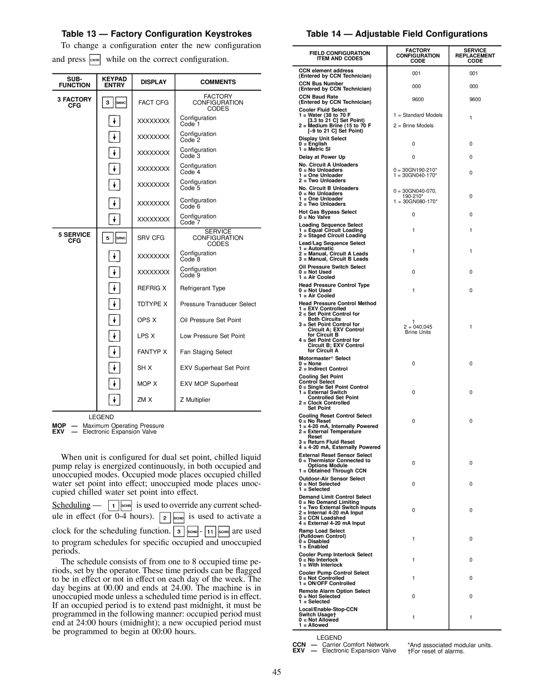
Table 13 Ð Factory Con®guration Keystrokes

To change a con®guration enter the new con®guration

and press while on the correct con®guration.


SUB-

KEYPAD

DISPLAY

COMMENTS

FUNCTION

ENTRY


3 FACTORY


FACTORY


FACT CFG

CONFIGURATION


CFG


CODES


XXXXXXXX

Con®guration


Code 1


XXXXXXXX

Con®guration


Code 2


XXXXXXXX

Con®guration


Code 3


XXXXXXXX

Con®guration


Code 4


XXXXXXXX

Con®guration


Code 5


XXXXXXXX

Con®guration


Code 6


XXXXXXXX

Con®guration


Code 7


5 SERVICE


SERVICE


SRV CFG

CONFIGURATION


CFG


CODES


XXXXXXXX

Con®guration


Code 8


XXXXXXXX

Con®guration


Code 9


REFRIG X

Refrigerant Type


TDTYPE X

Pressure Transducer Select


OPS X

Oil Pressure Set Point


LPS X

Low Pressure Set Point


FANTYP X

Fan Staging Select


SH X

EXV Superheat Set Point


MOP X

EXV MOP Superheat


ZM X

Z Multiplier


LEGEND


MOP

Ð Maximum Operating Pressure


EXV

Ð Electronic Expansion Valve


When unit is con®gured for dual set point, chilled liquid pump relay is energized continuously, in both occupied and unoccupied modes. Occupied mode places occupied chilled water set point into effect; unoccupied mode places unoc- cupied chilled water set point into effect.

Scheduling Ð

is used to override any current sched-

ule in effect (for 0-4 hours). is used to activate a

clock for the scheduling function. - are used

to program schedules for speci®c occupied and unoccupied periods.

The schedule consists of from one to 8 occupied time pe- riods, set by the operator. These time periods can be ¯agged to be in effect or not in effect on each day of the week. The day begins at 00.00 and ends at 24.00. The machine is in unoccupied mode unless a scheduled time period is in effect. If an occupied period is to extend past midnight, it must be programmed in the following manner: occupied period must end at 24:00 hours (midnight); a new occupied period must be programmed to begin at 00:00 hours.

Table 14 Ð Adjustable Field Con®gurations


FIELD CONFIGURATION


FACTORY

SERVICE


CONFIGURATION

REPLACEMENT


ITEM AND CODES


CODE

CODE


CCN element address


001

001

(Entered by CCN Technician)


CCN Bus Number


000

000

(Entered by CCN Technician)


CCN Baud Rate


9600

9600

(Entered by CCN Technician)


Cooler Fluid Select


1

= Water (38 to 70 F


1 = Standard Models

1


[3.3 to 21 C] Set Point)


2

= Medium Brine (15 to 70 F


2 = Brine Models


[±9 to 21 C] Set Point)


Display Unit Select


0

= English


0

0

1

= Metric SI


Delay at Power Up


0

0

No. Circuit A Unloaders


0

= No Unloaders


0 = 30GN190-210*

0

1

= One Unloader


1 = 30GN040-170*


2

= Two Unloaders


No. Circuit B Unloaders


0 = 30GN040-070,


0

= No Unloaders


190-210*

0

1

= One Unloader


1 = 30GN080-170*


2

= Two Unloaders


Hot Gas Bypass Select


0

0

0

= No Valve


Loading Sequence Select


1

= Equal Circuit Loading


1

1

2

= Staged Circuit Loading


Lead/Lag Sequence Select


1

= Automatic


1

1

2

= Manual, Circuit A Leads


3

= Manual, Circuit B Leads


Oil Pressure Switch Select


0

= Not Used


0

0

1

= Air Cooled


Head Pressure Control Type


0

= Not Used


1

0

1

= Air Cooled


Head Pressure Control Method


1

= EXV Controlled


2

= Set Point Control for


Both Circuits


1


3

= Set Point Control for


2 = 040,045

1


Circuit A; EXV Control


Brine Units


for Circuit B


4

= Set Point Control for


Circuit B; EXV Control


for Circuit A


Motormaster Select


0

= None


0

0

2

= Indirect Control


Cooling Set Point


Control Select


0

= Single Set Point Control


1

= External Switch


0

0


Controlled Set Point


2

= Clock Controlled


Set Point


Cooling Reset Control Select


0

= No Reset


0

0

1

= 4-20 mA, Internally Powered


2

= External Temperature


Reset


3

= Return Fluid Reset


4

= 4-20 mA, Externally Powered


External Reset Sensor Select


0

= Thermistor Connected to


0

0


Options Module


1

= Obtained Through CCN


Outdoor-Air Sensor Select


0

= Not Selected


0

0

1

= Selected


Demand Limit Control Select


0

= No Demand Limiting


1

= Two External Switch Inputs


0

0

2

= Internal 4-20 mA Input


3

= CCN Loadshed


4

= External 4-20 mA Input


Ramp Load Select


(Pulldown Control)


1

0

0

= Disabled


1

= Enabled


Cooler Pump Interlock Select


0

= No Interlock


1

0

1

= With Interlock


Cooler Pump Control Select


0

= Not Controlled


1

0

1

= ON/OFF Controlled


Remote Alarm Option Select


0

= Not Selected


0

0

1

= Selected


Local/Enable-Stop-CCN


Switch Usage²


1

1

0

= Not Allowed


1

= Allowed


LEGEND


CCN

Ð Carrier Comfort Network


*And associated modular units.

EXV

Ð Electronic Expansion Valve

²For reset of alarms.

45

Page 45
Image 45
Carrier 30GN040-420 operating instructions Factory Conguration Keystrokes, Adjustable Field Congurations

30GN040-420 specifications

The Carrier 30GN040-420 is a well-regarded model within the industry of chillers, designed to deliver efficient cooling solutions for a variety of commercial applications. Its compact design and advanced technology make it an ideal choice for businesses looking to optimize their HVAC systems.

One of the standout features of the Carrier 30GN series is its flexibility. This chiller model is available in a range of capacities, specifically from 40 to 420 tons, allowing for customized solutions based on specific cooling demands. Such versatility enables this unit to cater to a broad array of installations, from small commercial spaces to larger industrial facilities.

The Carrier 30GN040-420 utilizes a scroll compressor design, known for its reliability and efficiency. The scroll technology allows for a reduction in the number of moving parts, resulting in lower maintenance costs and increased durability. Additionally, the unit operates with environmentally friendly refrigerants such as R-410A, promoting sustainability without compromising performance.

Energy efficiency is another significant aspect of this model. The 30GN series is designed to provide high energy efficiency ratios (EER), which translates to lower operational costs for users over the lifespan of the unit. This is particularly beneficial in an era where energy costs are consistently rising.

The advanced controls found within the Carrier 30GN040-420 further enhance its performance and ease of use. The unit is equipped with a microprocessor-based control system that allows for precise temperature management while providing valuable diagnostic information. This feature not only improves the overall reliability of the system but also facilitates proactive maintenance, reducing the risk of unscheduled downtime.

Moreover, the design of the Carrier 30GN040-420 emphasizes quiet operation, making it suitable for environments where noise levels must be minimized. This characteristic is critical for applications in hospitals, schools, or office buildings, where a peaceful atmosphere is essential.

In summary, the Carrier 30GN040-420 chiller provides a robust solution for businesses requiring dependable and efficient cooling. Its features, including flexible capacity options, reliable scroll compressors, energy-efficient performance, advanced controls, and quiet operation, position it as a top choice for various commercial and industrial applications. As technology continues to evolve, models such as the 30GN series remain at the forefront, meeting the demands of modern HVAC needs while ensuring sustainability and efficiency.