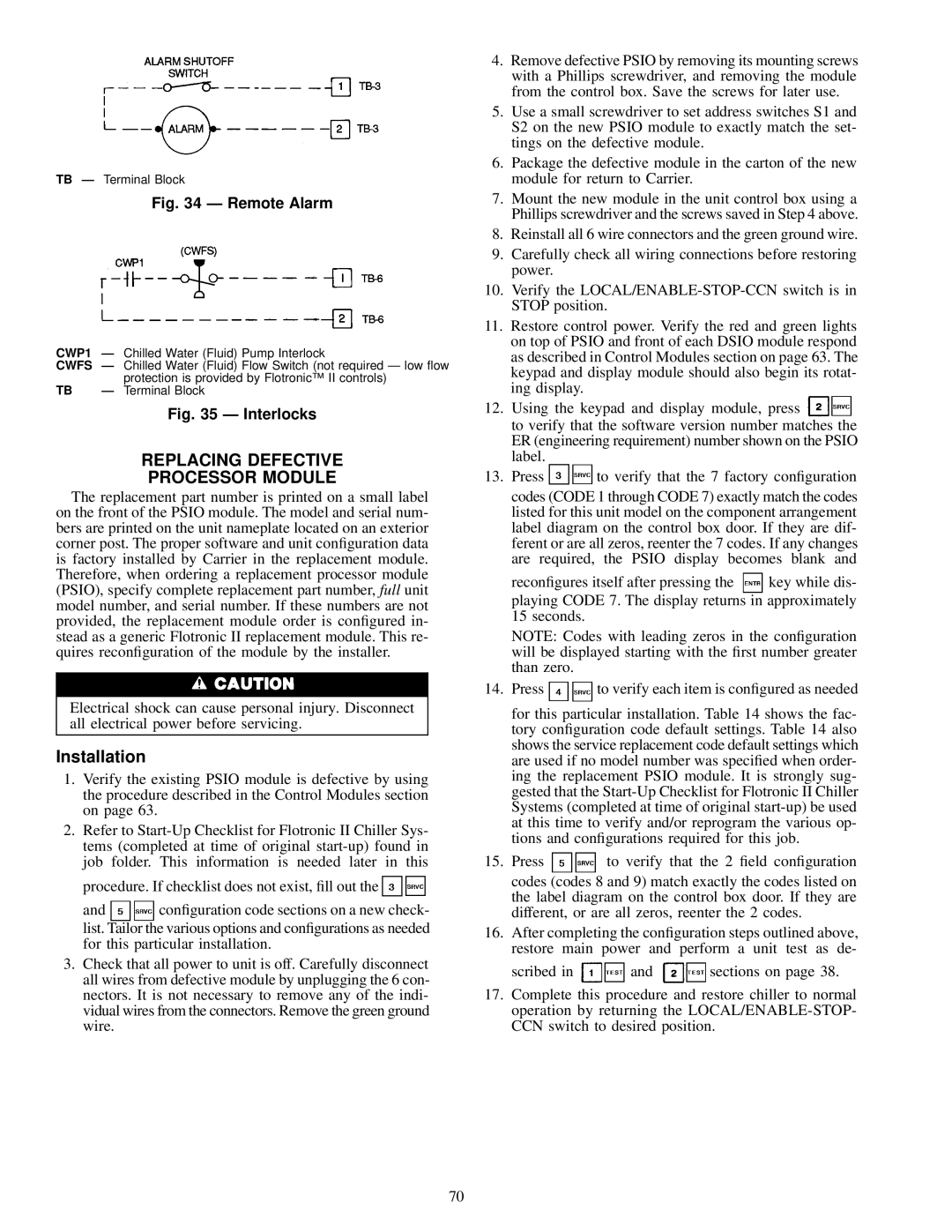
TB Ð Terminal Block

Fig. 34 Ð Remote Alarm

CWP1 Ð Chilled Water (Fluid) Pump Interlock

CWFS Ð Chilled Water (Fluid) Flow Switch (not required Ð low ¯ow


protection is provided by Flotronic™ II controls)

TB

Ð Terminal Block


Fig. 35 Ð Interlocks

REPLACING DEFECTIVE

PROCESSOR MODULE

The replacement part number is printed on a small label on the front of the PSIO module. The model and serial num- bers are printed on the unit nameplate located on an exterior corner post. The proper software and unit con®guration data is factory installed by Carrier in the replacement module. Therefore, when ordering a replacement processor module (PSIO), specify complete replacement part number, full unit model number, and serial number. If these numbers are not provided, the replacement module order is con®gured in- stead as a generic Flotronic II replacement module. This re- quires recon®guration of the module by the installer.

Electrical shock can cause personal injury. Disconnect all electrical power before servicing.

Installation

1.Verify the existing PSIO module is defective by using the procedure described in the Control Modules section on page 63.

2.Refer to Start-Up Checklist for Flotronic II Chiller Sys- tems (completed at time of original start-up) found in job folder. This information is needed later in this

procedure. If checklist does not exist, ®ll out the

and con®guration code sections on a new check- list. Tailor the various options and con®gurations as needed for this particular installation.

3.Check that all power to unit is off. Carefully disconnect all wires from defective module by unplugging the 6 con- nectors. It is not necessary to remove any of the indi- vidual wires from the connectors. Remove the green ground wire.

4.Remove defective PSIO by removing its mounting screws with a Phillips screwdriver, and removing the module from the control box. Save the screws for later use.

5.Use a small screwdriver to set address switches S1 and S2 on the new PSIO module to exactly match the set- tings on the defective module.

6.Package the defective module in the carton of the new module for return to Carrier.

7.Mount the new module in the unit control box using a Phillips screwdriver and the screws saved in Step 4 above.

8.Reinstall all 6 wire connectors and the green ground wire.

9.Carefully check all wiring connections before restoring power.

10.Verify the LOCAL/ENABLE-STOP-CCN switch is in STOP position.

11.Restore control power. Verify the red and green lights on top of PSIO and front of each DSIO module respond as described in Control Modules section on page 63. The keypad and display module should also begin its rotat- ing display.

12.Using the keypad and display module, press to verify that the software version number matches the ER (engineering requirement) number shown on the PSIO label.

13.Press to verify that the 7 factory con®guration codes (CODE 1 through CODE 7) exactly match the codes listed for this unit model on the component arrangement label diagram on the control box door. If they are dif- ferent or are all zeros, reenter the 7 codes. If any changes are required, the PSIO display becomes blank and

recon®gures itself after pressing the key while dis- playing CODE 7. The display returns in approximately 15 seconds.

NOTE: Codes with leading zeros in the con®guration will be displayed starting with the ®rst number greater than zero.

14.Press to verify each item is con®gured as needed for this particular installation. Table 14 shows the fac- tory con®guration code default settings. Table 14 also shows the service replacement code default settings which are used if no model number was speci®ed when order- ing the replacement PSIO module. It is strongly sug- gested that the Start-Up Checklist for Flotronic II Chiller Systems (completed at time of original start-up) be used at this time to verify and/or reprogram the various op- tions and con®gurations required for this job.

15.Press to verify that the 2 ®eld con®guration codes (codes 8 and 9) match exactly the codes listed on the label diagram on the control box door. If they are different, or are all zeros, reenter the 2 codes.

16.After completing the con®guration steps outlined above, restore main power and perform a unit test as de-

scribed in and sections on page 38.

17.Complete this procedure and restore chiller to normal operation by returning the LOCAL/ENABLE-STOP- CCN switch to desired position.

70

Page 70
Image 70
Carrier 30GN040-420 operating instructions Remote Alarm, Interlocks

30GN040-420 specifications

The Carrier 30GN040-420 is a well-regarded model within the industry of chillers, designed to deliver efficient cooling solutions for a variety of commercial applications. Its compact design and advanced technology make it an ideal choice for businesses looking to optimize their HVAC systems.

One of the standout features of the Carrier 30GN series is its flexibility. This chiller model is available in a range of capacities, specifically from 40 to 420 tons, allowing for customized solutions based on specific cooling demands. Such versatility enables this unit to cater to a broad array of installations, from small commercial spaces to larger industrial facilities.

The Carrier 30GN040-420 utilizes a scroll compressor design, known for its reliability and efficiency. The scroll technology allows for a reduction in the number of moving parts, resulting in lower maintenance costs and increased durability. Additionally, the unit operates with environmentally friendly refrigerants such as R-410A, promoting sustainability without compromising performance.

Energy efficiency is another significant aspect of this model. The 30GN series is designed to provide high energy efficiency ratios (EER), which translates to lower operational costs for users over the lifespan of the unit. This is particularly beneficial in an era where energy costs are consistently rising.

The advanced controls found within the Carrier 30GN040-420 further enhance its performance and ease of use. The unit is equipped with a microprocessor-based control system that allows for precise temperature management while providing valuable diagnostic information. This feature not only improves the overall reliability of the system but also facilitates proactive maintenance, reducing the risk of unscheduled downtime.

Moreover, the design of the Carrier 30GN040-420 emphasizes quiet operation, making it suitable for environments where noise levels must be minimized. This characteristic is critical for applications in hospitals, schools, or office buildings, where a peaceful atmosphere is essential.

In summary, the Carrier 30GN040-420 chiller provides a robust solution for businesses requiring dependable and efficient cooling. Its features, including flexible capacity options, reliable scroll compressors, energy-efficient performance, advanced controls, and quiet operation, position it as a top choice for various commercial and industrial applications. As technology continues to evolve, models such as the 30GN series remain at the forefront, meeting the demands of modern HVAC needs while ensuring sustainability and efficiency.