LOCAL/ENABLE-STOP-CCN switch. Most probable cause of this fault is shutdown or failure of chilled ¯uid pump to start. Other possibilities are improper con®guration or wir- ing errors.

Code 55 Cooler pump interlock failure Ð Contacts closed when pump is off (alarm)

If the unit is con®gured for cooler pump control and cooler pump interlock, and the interlock is closed when the cooler pump relay is off, the cooler pump shall be shut down and the unit prevented from starting. Reset is manual with the LOCAL/ENABLE-STOP-CCN switch.

Possible causes are:

1.Interlock switch fails to close within one minute after chilled water pump starts

2.Interlock switch opens during unit operation

3.Interlock voltage is detected, but unit is not con®gured for interlock

4.Interlock voltage is outside its valid range

If any of these conditions occur, all compressors are dis- abled and, if running, shutdown occurs without pumpout. Chilled ¯uid pump also shuts down. Reset is manual, with LOCAL/ENABLE-STOP-CCN switch. Most probable cause of this fault is shutdown or failure of chilled ¯uid pump to start. Other possibilities are improper con®guration or wir- ing errors.

Code 56 Water System Manager (WSM) communication failure (alert)

If the WSM has previously established communications with the control and the WSM is not disabled and has not communicated with the control within the last 5 minutes, the control will remove all WSM forces from the chillers vari- ables. The chiller will continue to operate on a stand-alone basis. Reset is automatic when the WSM re-establishes com- munication with the unit.

Code 57 Calibration required for discharge pressure trans- ducer, circuit A (alert)

Code 58 Calibration required for discharge pressure trans- ducer, circuit B (alert)

If the discharge pressure transducer has not been success- fully calibrated, the circuit will not start. Reset is automatic upon successful calibration of the transducer.

Code 59 Calibration required for suction pressure trans- ducer, circuit A (alert)

Code 60 Calibration required for suction pressure trans- ducer, circuit B (alert

If the suction pressure transducer has not been success- fully calibrated, the circuit will not start. Reset is automatic upon successful calibration of the transducer.

Code 61 Calibration required for oil pressure transducer, circuit A (alert)

Code 62 Calibration required for oil pressure transducer, circuit B (alert)

If the oil pressure transducer has not been successfully calibrated, the circuit will not start. Reset is automatic upon successful calibration of the transducer.

Code 63 Complete unit shutdown due to failure (alarm)

This alarm alerts the user that the unit is totally shut down due to one or more fault conditions. Reset is automatic when all alarms causing complete unit shutdown are reset.

Code 64 Loss of charge, circuit A (alert) Code 65 Loss of charge, circuit B (alert)

If the unit uses suction and discharge transducers with the same part number, and the discharge pressure is below 10 psig when the unit is shut down, the circuit will not start. Reset is automatic when the discharge pressure rises above

15 psig. This alarm does not function in units using different part number transducers for suction and discharge pressure, since the discharge transducer in that application does not function below 20 psig.

Code 66 Flotronic™ System Manager loss of communi- cations (alarm)

If the FSM has established communication with the con- trol, and the communication is subsequently lost for more than 20 seconds, the control will remove all forces on the chiller variables. Control of the unit will revert to stand- alone basis, and reset is automatic upon re-establishment of communication.

Code 67 Transducer calibration failure due to incorrect date code (alarm)

This applies to units having pressure transducers with the same part number for both suction and discharge pressures. If the transducer calibration is attempted and the factory de- fault date code (Jan. 1, 1980) is in the date variable, then the unit will not start. Reset is automatic when the proper date code is entered upon calibration.

Code 70 High leaving chilled ¯uid temperature (alert)

If the leaving chilled ¯uid temperature is rising and is

higher than the limit established in the subfunction

and the unit is at full capacity then alert 70 will be activated. The unit will continue to function normally, and reset will be automatic upon leaving chilled ¯uid temperature drop- ping to 5° F below the limit or less than control set point.

Electronic Expansion Valve (EXV)

NOTE: This applies to all units except 30GN040 and 045 with optional brine. The 040 and 045 units with optional brine have TXVs.

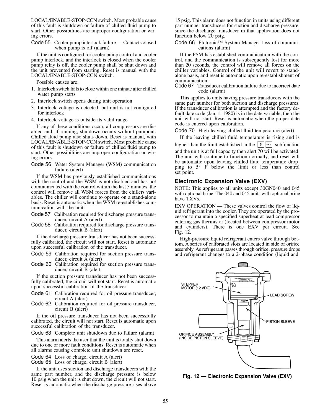
EXV OPERATION Ð These valves control the ¯ow of liq- uid refrigerant into the cooler. They are operated by the pro- cessor to maintain a speci®ed superheat at lead compressor entering gas thermistor (located between compressor motor and cylinders). There is one EXV per circuit. See Fig. 12.

High-pressure liquid refrigerant enters valve through bot- tom. A series of calibrated slots are located in side of ori®ce assembly. As refrigerant passes through ori®ce, pressure drops and refrigerant changes to a 2-phase condition (liquid and

Fig. 12 Ð Electronic Expansion Valve (EXV)

55

Page 55
Image 55
Carrier 30GN040-420 operating instructions Electronic Expansion Valve EXV

30GN040-420 specifications

The Carrier 30GN040-420 is a well-regarded model within the industry of chillers, designed to deliver efficient cooling solutions for a variety of commercial applications. Its compact design and advanced technology make it an ideal choice for businesses looking to optimize their HVAC systems.

One of the standout features of the Carrier 30GN series is its flexibility. This chiller model is available in a range of capacities, specifically from 40 to 420 tons, allowing for customized solutions based on specific cooling demands. Such versatility enables this unit to cater to a broad array of installations, from small commercial spaces to larger industrial facilities.

The Carrier 30GN040-420 utilizes a scroll compressor design, known for its reliability and efficiency. The scroll technology allows for a reduction in the number of moving parts, resulting in lower maintenance costs and increased durability. Additionally, the unit operates with environmentally friendly refrigerants such as R-410A, promoting sustainability without compromising performance.

Energy efficiency is another significant aspect of this model. The 30GN series is designed to provide high energy efficiency ratios (EER), which translates to lower operational costs for users over the lifespan of the unit. This is particularly beneficial in an era where energy costs are consistently rising.

The advanced controls found within the Carrier 30GN040-420 further enhance its performance and ease of use. The unit is equipped with a microprocessor-based control system that allows for precise temperature management while providing valuable diagnostic information. This feature not only improves the overall reliability of the system but also facilitates proactive maintenance, reducing the risk of unscheduled downtime.

Moreover, the design of the Carrier 30GN040-420 emphasizes quiet operation, making it suitable for environments where noise levels must be minimized. This characteristic is critical for applications in hospitals, schools, or office buildings, where a peaceful atmosphere is essential.

In summary, the Carrier 30GN040-420 chiller provides a robust solution for businesses requiring dependable and efficient cooling. Its features, including flexible capacity options, reliable scroll compressors, energy-efficient performance, advanced controls, and quiet operation, position it as a top choice for various commercial and industrial applications. As technology continues to evolve, models such as the 30GN series remain at the forefront, meeting the demands of modern HVAC needs while ensuring sustainability and efficiency.