Chapter 3 Installing the Router
Connecting to the Console and Auxiliary Ports
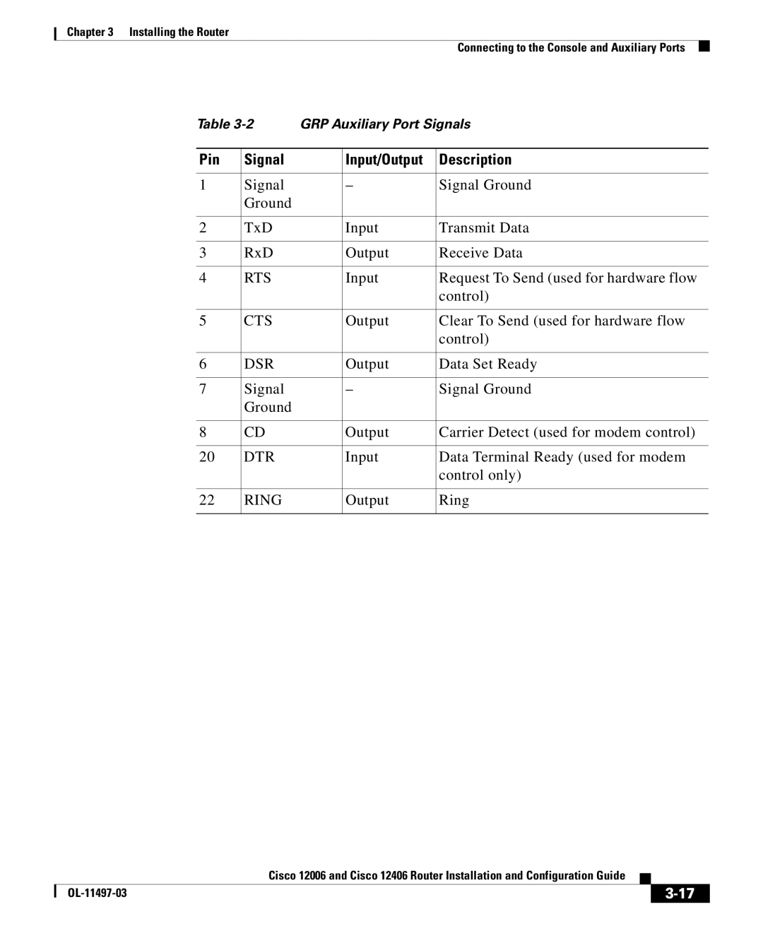
Table | GRP Auxiliary Port Signals | |||
|
|
|
|
|
Pin | Signal |
| Input/Output | Description |
|
|
|
|
|
1 | Signal |
| – | Signal Ground |
| Ground |
|
|
|
|
|
|
|
|
2 | TxD |
| Input | Transmit Data |
|
|
|
|
|
3 | RxD |
| Output | Receive Data |
|
|
|
|
|
4 | RTS |
| Input | Request To Send (used for hardware flow |
|
|
|
| control) |
|
|
|
|
|
5 | CTS |
| Output | Clear To Send (used for hardware flow |
|
|
|
| control) |
|
|
|
|
|
6 | DSR |
| Output | Data Set Ready |
|
|
|
|
|
7 | Signal |
| – | Signal Ground |
| Ground |
|
|
|
|
|
|
|
|
8 | CD |
| Output | Carrier Detect (used for modem control) |
|
|
|
|
|
20 | DTR |
| Input | Data Terminal Ready (used for modem |
|
|
|
| control only) |
|
|
|
|
|
22 | RING |
| Output | Ring |
|
|
|
|
|
|
| Cisco 12006 and Cisco 12406 Router Installation and Configuration Guide |
|
|
|
|
| ||
|
|
| ||
|
|
|