Chapter 3 Installing the Router
Connecting to a DC Power Source
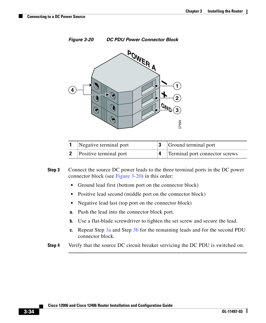
Figure 3-20 DC PDU Power Connector Block
POWER A
4 ![]()


 +
+ 

 GND
GND
1
2
3
57993
1 | Negative terminal port | 3 | Ground terminal port |
|
|
|
|
2 | Positive terminal port | 4 | Terminal port connector screws |
|
|
|
|
Step 3 Connect the source DC power leads to the three terminal ports in the DC power connector block (see Figure
•Ground lead first (bottom port on the connector block)
•Positive lead second (middle port on the connector block)
•Negative lead last (top port on the connector block)
a.Push the lead into the connector block port.
b.Use a
c.Repeat Step 3a and Step 3b for the remaining leads and for the second PDU connector block.
Step 4 Verify that the source DC circuit breaker servicing the DC PDU is switched on.
| Cisco 12006 and Cisco 12406 Router Installation and Configuration Guide |
|