Chapter 3 Installing the Router
Connecting to a DC Power Source
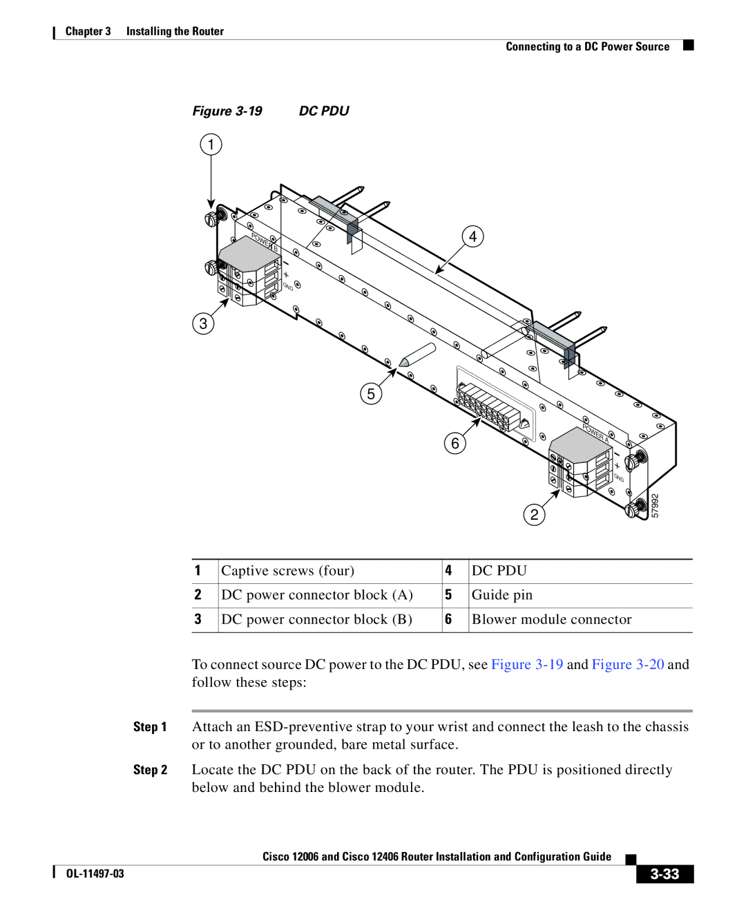
Figure | DC PDU |
1
POWER B
![]() +
+
![]() GND
GND ![]()
3
5
4
6
2
POWER A![]()
![]()
![]() +
+ ![]()
![]() GND
GND
57992
1 | Captive screws (four) | 4 | DC PDU |
|
|
|
|
2 | DC power connector block (A) | 5 | Guide pin |
|
|
|
|
3 | DC power connector block (B) | 6 | Blower module connector |
|
|
|
|
To connect source DC power to the DC PDU, see Figure
Step 1 Attach an
Step 2 Locate the DC PDU on the back of the router. The PDU is positioned directly below and behind the blower module.
|
| Cisco 12006 and Cisco 12406 Router Installation and Configuration Guide |
|
|
|
|
| ||
|
|
| ||
|
|
|