Chapter 3 Installing the Router
Connecting to the Console and Auxiliary Ports
Table | PRP | ||
|
|
| |
Ethernet Port Pin | Signal | Description | |
|
|
|
|
6 |
| RxD– | Receive data – |
|
|
|
|
7 |
| Termination Network | No connection |
|
|
|
|
8 |
| Termination Network | No connection |
|
|
|
|
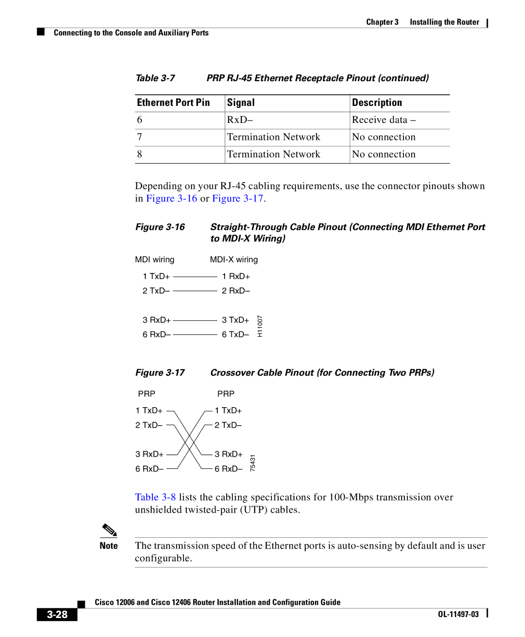
Depending on your
Figure
MDI wiring
1TxD+
2TxD–
3RxD+
6RxD–
1 RxD+
2 RxD–
6 TxD– | H11007 |
3 TxD+ |
|
Figure
PRP
1TxD+
2TxD–
3RxD+
6RxD–
Crossover Cable Pinout (for Connecting Two PRPs)
PRP
1 TxD+
2 TxD–
3 RxD+ | 75431 |
6 RxD– |
Table
Note The transmission speed of the Ethernet ports is
| Cisco 12006 and Cisco 12406 Router Installation and Configuration Guide |
|