Chapter 3 Installing the Router
Connecting to an AC Power Source
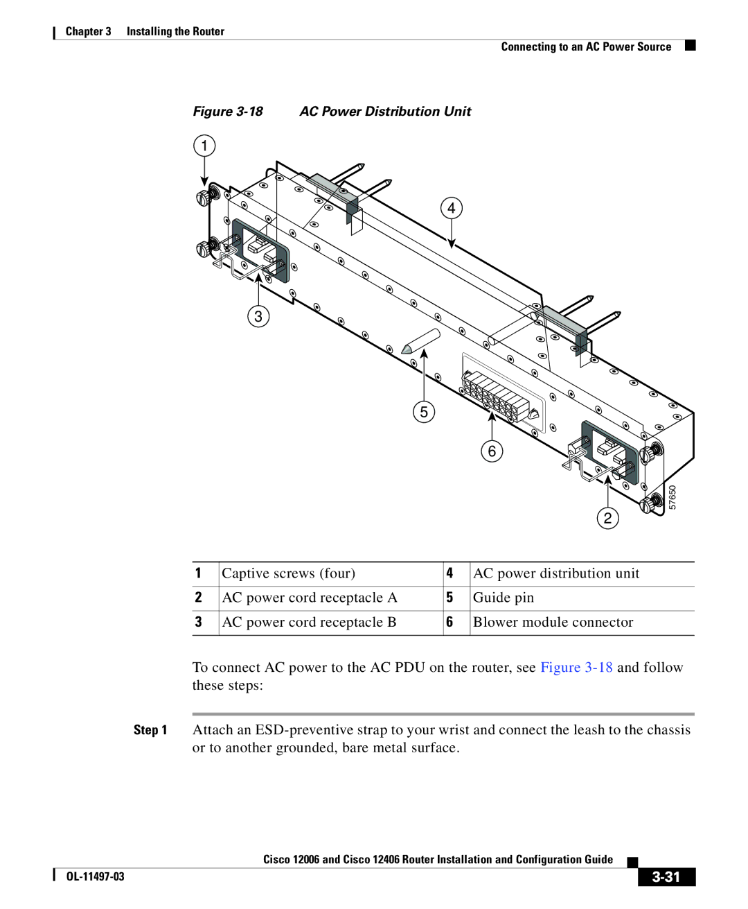
Figure 3-18 AC Power Distribution Unit
1
4
3
5
|
|
| 6 |
|
|
| 57650 |
|
|
| 2 |
1 | Captive screws (four) | 4 | AC power distribution unit |
2 | AC power cord receptacle A | 5 | Guide pin |
3 | AC power cord receptacle B | 6 | Blower module connector |
To connect AC power to the AC PDU on the router, see Figure
Step 1 Attach an
|
| Cisco 12006 and Cisco 12406 Router Installation and Configuration Guide |
|
|
|
|
| ||
|
|
| ||
|
|
|