Chapter 3 Installing the Router
Power On the Router
Note In a noisy environment, the blowers might be difficult to hear; in that case, place your hand in front of the exhaust vents at the rear of the chassis to verify that the blowers are operating.
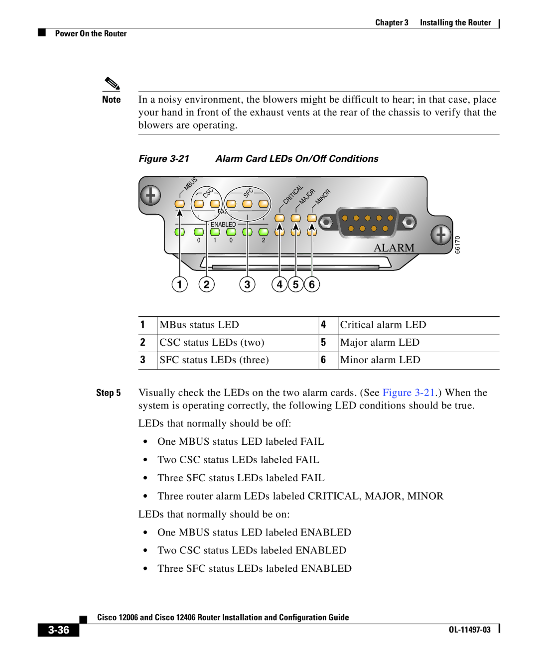
Figure 3-21 Alarm Card LEDs On/Off Conditions
MBUS | CSC |
| SFC |
| CRITICALMAJOR | MINOR |
| |
|
|
|
| |||||
|
|
|
|
|
|
| ||
|
| FAIL |
|
|
|
|
|
|
| ENABLED |
|
|
|
|
| 66170 | |
0 | 1 | 0 | 1 | 2 |
|
| ALARM | |
|
|
|
| |||||
1 | 2 |
| 3 | 4 | 5 | 6 |
|
|
1 | MBus status LED | 4 | Critical alarm LED |
|
|
|
|
2 | CSC status LEDs (two) | 5 | Major alarm LED |
|
|
|
|
3 | SFC status LEDs (three) | 6 | Minor alarm LED |
|
|
|
|
Step 5 Visually check the LEDs on the two alarm cards. (See Figure
LEDs that normally should be off:
•One MBUS status LED labeled FAIL
•Two CSC status LEDs labeled FAIL
•Three SFC status LEDs labeled FAIL
•Three router alarm LEDs labeled CRITICAL, MAJOR, MINOR LEDs that normally should be on:
•One MBUS status LED labeled ENABLED
•Two CSC status LEDs labeled ENABLED
•Three SFC status LEDs labeled ENABLED
Cisco 12006 and Cisco 12406 Router Installation and Configuration Guide
| ||
|