Configuring Data-Link Switching Plus
DLSw+ Configuration Task List
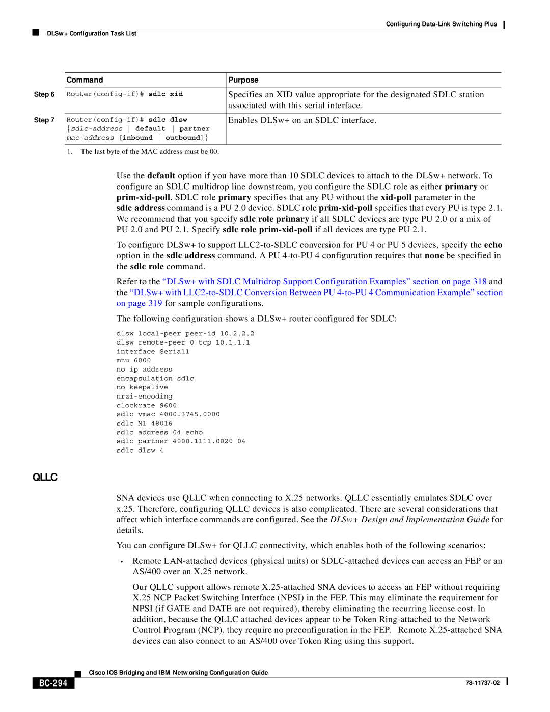
| Command | Purpose |
Step 6 | | |
Router(config-if)# sdlc xid | Specifies an XID value appropriate for the designated SDLC station |
| | associated with this serial interface. |
Step 7 | | |
Router(config-if)# sdlc dlsw | Enables DLSw+ on an SDLC interface. |
| {sdlc-addressdefault partner | |
| mac-address[inbound outbound]} | |
| | |
| 1. The last byte of the MAC address must be 00. | |
Use the default option if you have more than 10 SDLC devices to attach to the DLSw+ network. To configure an SDLC multidrop line downstream, you configure the SDLC role as either primary or prim-xid-poll. SDLC role primary specifies that any PU without the xid-pollparameter in the
sdlc address command is a PU 2.0 device. SDLC role prim-xid-pollspecifies that every PU is type 2.1. We recommend that you specify sdlc role primary if all SDLC devices are type PU 2.0 or a mix of PU 2.0 and PU 2.1. Specify sdlc role prim-xid-pollif all devices are type PU 2.1.
To configure DLSw+ to support LLC2-to-SDLC conversion for PU 4 or PU 5 devices, specify the echo option in the sdlc address command. A PU 4-to-PU 4 configuration requires that none be specified in the sdlc role command.
Refer to the “DLSw+ with SDLC Multidrop Support Configuration Examples” section on page 318 and the “DLSw+ with LLC2-to-SDLC Conversion Between PU 4-to-PU 4 Communication Example” section on page 319 for sample configurations.
The following configuration shows a DLSw+ router configured for SDLC:
dlsw local-peer peer-id 10.2.2.2 dlsw remote-peer 0 tcp 10.1.1.1 interface Serial1
mtu 6000
no ip address encapsulation sdlc no keepalive nrzi-encoding clockrate 9600
sdlc vmac 4000.3745.0000 sdlc N1 48016
sdlc address 04 echo
sdlc partner 4000.1111.0020 04 sdlc dlsw 4
QLLC
SNA devices use QLLC when connecting to X.25 networks. QLLC essentially emulates SDLC over x.25. Therefore, configuring QLLC devices is also complicated. There are several considerations that affect which interface commands are configured. See the DLSw+ Design and Implementation Guide for details.
You can configure DLSw+ for QLLC connectivity, which enables both of the following scenarios:
•Remote LAN-attached devices (physical units) or SDLC-attached devices can access an FEP or an AS/400 over an X.25 network.
Our QLLC support allows remote X.25-attached SNA devices to access an FEP without requiring X.25 NCP Packet Switching Interface (NPSI) in the FEP. This may eliminate the requirement for NPSI (if GATE and DATE are not required), thereby eliminating the recurring license cost. In addition, because the QLLC attached devices appear to be Token Ring-attached to the Network Control Program (NCP), they require no preconfiguration in the FEP. Remote X.25-attached SNA devices can also connect to an AS/400 over Token Ring using this support.
| Cisco IOS Bridging and IBM Networking Configuration Guide |
BC-294 | 78-11737-02 |