Configuring
DLSw+ Configuration Examples
clockrate 19200 sdlc role primary
sdlc vmac 4000.1234.5600 sdlc address C1
sdlc xid C1 05DCCCC1
sdlc partner 4001.3745.1088 C1 sdlc address C2
In the following example, all devices are type PU 2.1 (Method 1):
interface serial 2 mtu 4400
no ip address encapsulation sdlc no keepalive clockrate 19200 sdlc role primary
sdlc vmac 4000.1234.5600 sdlc address C1
In the following example, all devices are type PU 2.1 (Method 2):
interface serial 2 mtu 4400
no ip address encapsulation sdlc no keepalive clockrate 19200
sdlc role
sdlc partner 4001.3745.1088 C1 sdlc address C2
sdlc partner 4001.3745.1088 C2 sdlc dlsw C1 C2
DLSw+ with
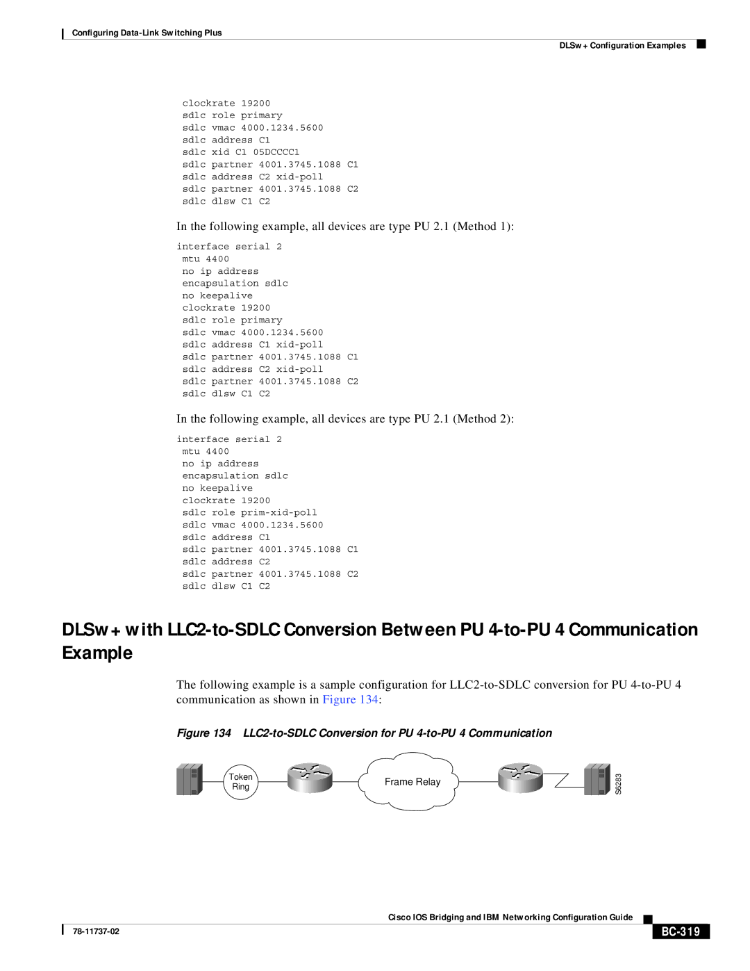
The following example is a sample configuration for
Figure 134 LLC2-to-SDLC Conversion for PU 4-to-PU 4 Communication
Token | Frame Relay | |
Ring | ||
|
S6283
|
| Cisco IOS Bridging and IBM Networking Configuration Guide |
|
|
|
|
|
| |||
|
|
|
|
| |
|
|
|
|