Configuring
DLSw+ Configuration Examples
DLSw+ with Enhanced Load Balancing Configuration Example
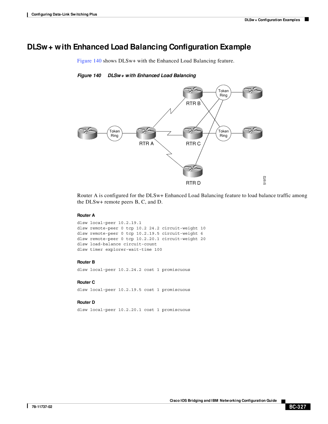
Figure 140 shows DLSw+ with the Enhanced Load Balancing feature.
Figure 140 DLSw+ with Enhanced Load Balancing
Token
Ring
RTR B
Token | Token |
Ring | Ring |
RTR A | RTR C |
RTR D
51972
Router A is configured for the DLSw+ Enhanced Load Balancing feature to load balance traffic among the DLSw+ remote peers B, C, and D.
Router A
dlsw
dlsw
dlsw timer
Router B
dlsw
Router C
dlsw
Router D
dlsw
|
| Cisco IOS Bridging and IBM Networking Configuration Guide |
|
|
|
|
|
| |||
|
|
|
|
| |
|
|
|
|