Configuring
DLSw+ Configuration Examples
Example 3
In this example, two different X.25 resources want to communicate over X.25 to the same FEP.
In the router attached to the X.25 network, every X.25 connection request for X.121 address 31102150101 is directed to DLSw+. The first SVC to be established will be mapped to virtual MAC address 1000.0000.0001. The second SVC to be established will be mapped to virtual MAC address 1000.0000.0002.
interface serial 0 encapsulation x25 x25 address 31102
x25 map qllc 33204
x25 map qllc 35765
qllc dlsw subaddress 150101 vmacaddr 1000.0000.0001 2 partner 4000.1611.1234
DLSw+ with RIF Passthrough Configuration Example
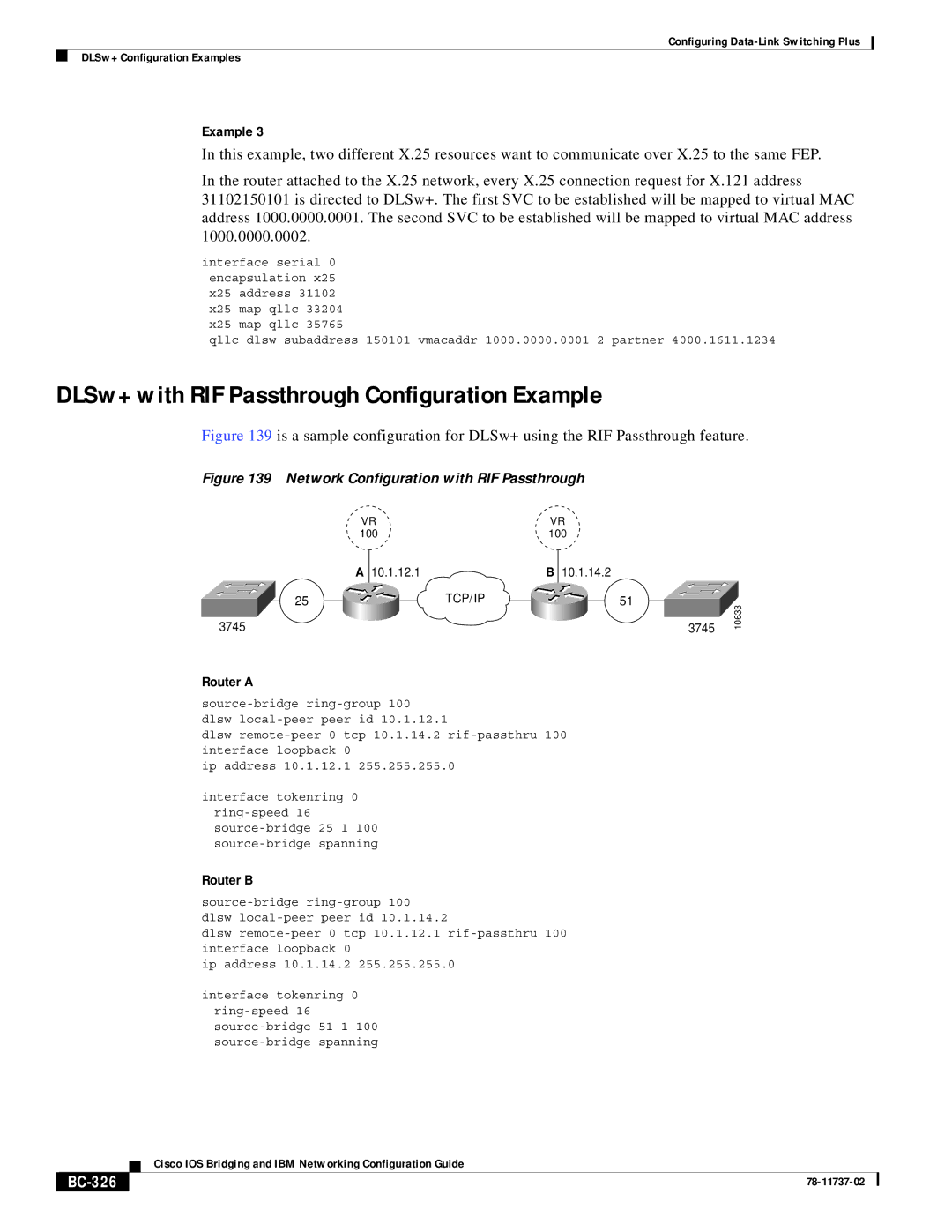
Figure 139 is a sample configuration for DLSw+ using the RIF Passthrough feature.
Figure 139 Network Configuration with RIF Passthrough
VR |
| VR |
100 |
| 100 |
A 10.1.12.1 |
| B 10.1.14.2 |
25 | TCP/IP | 51 |
3745 |
| 3745 |
10633
Router A
dlsw
dlsw
ip address 10.1.12.1 255.255.255.0
interface tokenring 0
Router B
dlsw
dlsw
ip address 10.1.14.2 255.255.255.0
interface tokenring 0
| Cisco IOS Bridging and IBM Networking Configuration Guide |
|