Configuring
DLSw+ Configuration Examples
The following output of the show ip rsvp res command on the DLSWRTR1 verifies that the RSVP reservation was successful:
DLSWRTR1#show ip rsvp rese |
|
|
|
|
|
|
|
| |
To | From | Pro DPort | Sport Next Hop | I/F | Fi Serv BPS Bytes | ||||
10.2.17.1 | 10.14.25.2 | TCP | 2065 | 11003 10.14.25.2 | Et1/1 FF | RATE | 10K | 28K | |
10.14.25.2 | 10.2.17.1 | TCP | 11003 | 2065 |
| FF | RATE | 10K | 28K |
DLSw+ with Ethernet Redundancy Configuration Example
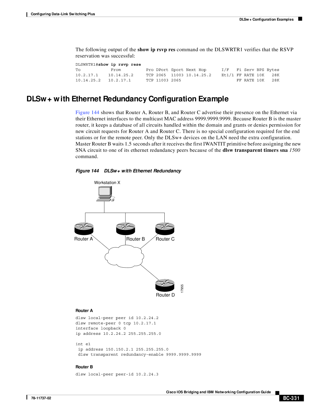
Figure 144 shows that Router A, Router B, and Router C advertise their presence on the Ethernet via their Ethernet interfaces to the multicast MAC address 9999.9999.9999. Because Router B is the master router, it keeps a database of all circuits handled within the domain and grants or denies permission for new circuit requests for Router A and Router C. There is no special configuration required for the end stations or for the remote peer. Only the DLSw+ devices on the LAN need the extra configuration. Master Router B waits 1.5 seconds after it receives the first IWANTIT primitive before assigning the new SNA circuit to one of its ethernet redundancy peers because of the dlsw transparent timers sna 1500 command.
Figure 144 DLSw+ with Ethernet Redundancy
Workstation X
Router A | Router B | Router C |
17955
Router D
Router A
dlsw
ip address 10.2.24.2 255.255.255.0
int e1
ip address 150.150.2.1 255.255.255.0
dlsw transparent
Router B
dlsw
|
| Cisco IOS Bridging and IBM Networking Configuration Guide |
|
|
|
|
|
| |||
|
|
|
|
| |
|
|
|
|