Configuring
DLSw+ Configuration Examples
DLSw+ RSVP Bandwidth Reservation Feature with Border Peers Configuration Example
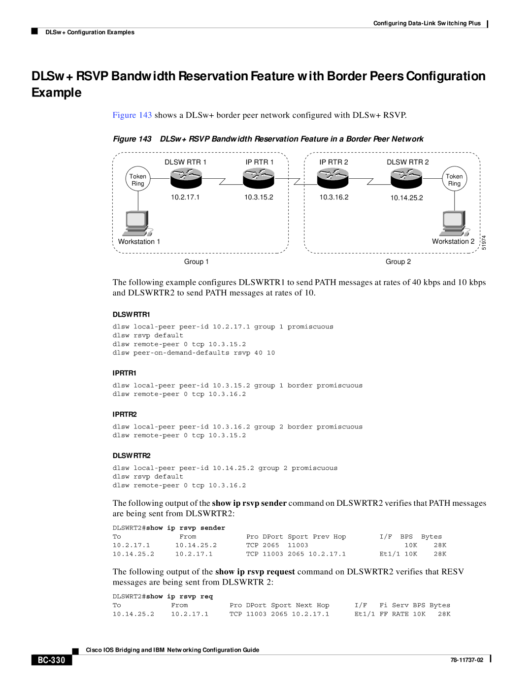
Figure 143 shows a DLSw+ border peer network configured with DLSw+ RSVP.
Figure 143 DLSw+ RSVP Bandwidth Reservation Feature in a Border Peer Network
|
|
|
| DLSW RTR 1 | IP RTR 1 | IP RTR 2 | DLSW RTR | 2 |
|
|
|
| Token |
|
|
|
|
| Token | ||||
| Ring |
|
|
|
|
| Ring | ||||
| 10.2.17.1 | 10.3.15.2 | 10.3.16.2 | 10.14.25.2 |
|
|
|
| |||
|
|
|
|
|
|
|
|
|
|
|
|
|
|
|
|
|
|
|
|
|
|
|
|
|
|
|
|
|
|
|
|
|
|
|
|
|
|
|
|
|
|
|
|
|
|
|
|
Workstation 1 | Workstation 2 |
Group 1 | Group 2 |
51974
The following example configures DLSWRTR1 to send PATH messages at rates of 40 kbps and 10 kbps and DLSWRTR2 to send PATH messages at rates of 10.
DLSWRTR1
dlsw
dlsw
dlsw
IPRTR1
dlsw
IPRTR2
dlsw
DLSWRTR2
dlsw
dlsw
The following output of the show ip rsvp sender command on DLSWRTR2 verifies that PATH messages are being sent from DLSWRTR2:
DLSWRT2#show ip rsvp sender |
|
|
|
|
| |
To | From | Pro DPort | Sport Prev Hop | I/F BPS | Bytes | |
10.2.17.1 | 10.14.25.2 | TCP | 2065 | 11003 | 10K | 28K |
10.14.25.2 | 10.2.17.1 | TCP | 11003 | 2065 10.2.17.1 | Et1/1 10K | 28K |
The following output of the show ip rsvp request command on DLSWRTR2 verifies that RESV messages are being sent from DLSWRTR 2:
|
|
| DLSWRT2#show ip rsvp req |
|
|
|
|
|
|
| |
|
|
| To | From | Pro DPort Sport Next Hop | I/F | Fi | Serv | BPS | Bytes | |
10.14.25.2 | 10.2.17.1 | TCP 11003 2065 10.2.17.1 | Et1/1 FF | RATE | 10K | 28K | |||||
|
|
| Cisco IOS Bridging and IBM Networking Configuration Guide |
|
|
|
|
|
| ||
|
|
|
|
|
|
|
|
| |||
|
|
|
|
|
|
|
|
|
|
|
|
|
|
|
|
|
|
|
|
|
|
| |
|
|
|
|
|
|
|
|
|
| ||