CF2001P
NEXT
■Checking the Hole-Punching Positions for FN-107
NOTE
•For details on the installing
•To adjust
•To exit the External Panel Controller, refer to step 14 on page 24.
1.Unplug the power cord, and then turn off the printer.
2.Load
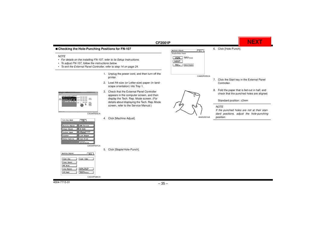
6. Click
C4683P005CA
7.Click the Start key in the External Panel Controller.
3.Check that the External Panel Controller appears in the computer screen, and then display the Tech. Rep. Mode screen. (For details about displaying the Tech. Rep. Mode screen, refer to the Service Manual.)
C4004P565CA
4. Click [Machine Adjust].
8.Fold the paper that is fed out in half, and check that the punched holes are aligned.
Standard position: ±2mm
NOTE
If the punched holes are not at their stan- dard positions, adjust the
4643U031AA position.
C4004P597CA
5. Click
C4004P588CA
– 35 – | |
|