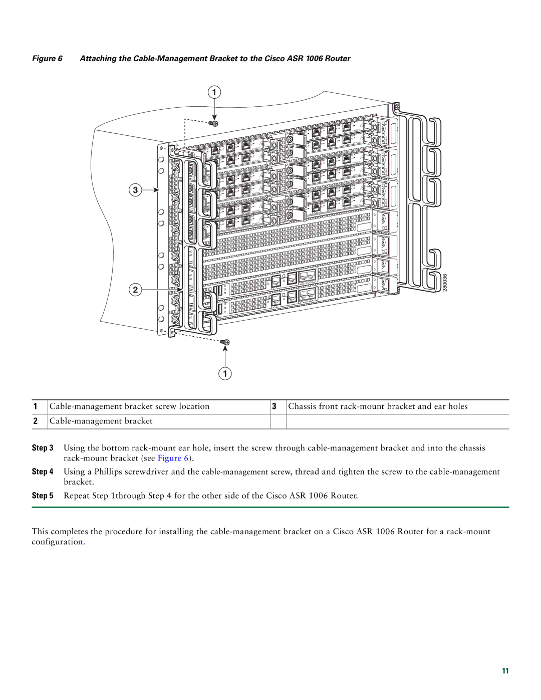
Figure 6 Attaching the Cable-Management Bracket to the Cisco ASR 1006 Router
1
3
2
|
|
|
| C/A | |
|
| C/ | A |
| /L |
C/A | A | /L |
| 3 | |
A | /L |
|
| 2 |
|
|
|
|
| ||
|
| 1 |
| C/A | |
|
|
|
| ||
0 |
| C/ | A | A/L | |
|
|
| |||
C/ | A | A | /L |
| 3 |
|
|
| |||
A | /L |
|
| 2 |
|
|
|
|
| ||
|
| 1 |
|
|
|
0 |
|
|
|
|
|
|
|
|
| C/A |
C/A | C/A | A/L | ||
A | /L | 3 | ||
A/L |
|
| 2 | |
|
| 1 |
| C /A |
0 |
| C/A | A/L | |
|
| |||
C/ | A | A | /L | 3 |
A | /L |
|
| 2 |
|
|
| ||
|
| 1 |
|
|
0 |
|
|
|
|
|
|
|
| C/A |
C/A | C/A | A/L | ||
A | /L | 3 | ||
A | /L |
|
| 2 |
|
|
| ||
|
| 1 |
| C/A |
0 |
| C/A | A/L | |
|
| |||
C/ | A | A | /L | 3 |
A/L |
|
| 2 | |
|
| 1 |
|
|
0 |
|
|
|
|
C /A |
| T AT | US |
A/L | S |
| |
|
|
|
C /A |
| TATUS |
A/L | S | |
|
|
C/A |
| TATUS | ||||
A | /L | S | ||||
|
|
| ||||
|
|
|
|
| ||
C/A |
| T A | T | US | ||
A/L | S |
|
| |||
|
|
| ||||
|
|
|
|
| ||
C/ | A |
| TATUS | |||
A | /L | S |
|
|
| |
|
|
|
|
| ||
C/ | A |
|
|
| US | |
| /L | S | T | AT |
| |
A |
|
|
| |||
|
|
|
|
| ||
|
|
|
| C/A | |
|
| C | /A | A/L | |
C/A | A/L |
|
| ||
A | /L |
|
| 2 |
|
|
|
|
| ||
|
| 1 |
| C | /A |
0 |
| C | /A | A/L | |
|
|
| |||
C/A | A/L |
|
| ||
A | /L |
|
| 2 |
|
|
|
|
| ||
|
| 1 |
|
|
|
0 |
|
|
|
|
|
|
|
|
| C/A | |
|
| C | /A | A | /L |
|
|
| |||
C/A | A | /L |
|
| |
A | /L |
|
| 2 |
|
|
| 1 |
| C/ | A |
|
|
|
|
| |
0 |
| C | /A | A | /L |
C | /A | A | /L |
|
|
A/L |
|
| 2 |
| |
|
| 1 |
|
|
|
0 |
|
|
|
|
|
|
|
|
| C/A | |
|
| C | /A | A/L | |
C | /A | A/L |
|
| |
A/L |
|
| 2 |
| |
|
| 1 |
| C/A | |
|
|
|
| ||
0 |
| C/A | A/L | ||
|
| ||||
C/A | A | /L |
|
| |
A/L |
|
| 2 |
| |
|
| 1 |
|
|
|
0 |
|
|
|
|
|
C/ | A |
| US |
| T AT | ||
A/L |
| ||
S |
| ||
|
|
|
| ||
3 |
|
|
|
|
|
C/ | A |
|
| TATUS | |
A/L |
| S |
|
| |
|
|
|
| ||
|
|
|
|
| |
3 |
|
|
|
|
|
C/ | A |
|
| TATUS | |
A | /L |
| S |
|
|
|
|
|
| ||
3 |
|
|
|
|
|
C/A |
|
| T AT | US | |
| /L |
| S |
| |
A |
|
|
| ||
|
|
|
| ||
3 |
|
|
|
|
|
C/ | A |
|
| TATUS | |
A | /L |
| S |
|
|
|
|
|
| ||
3 |
|
|
|
|
|
C/ | A |
|
|
| US |
|
|
| T AT | ||
| /L |
| S |
| |
A |
|
|
| ||
|
|
|
| ||
3 |
|
|
|
|
|
 280036
1
1
2
3 Chassis front |
Step 3 Using the bottom
Step 4 Using a Phillips screwdriver and the
Step 5 Repeat Step 1through Step 4 for the other side of the Cisco ASR 1006 Router.
This completes the procedure for installing the
11