Chassis Ground Connection Installation
Before you connect power or turn on power to your router, you must provide an adequate chassis ground (earth) connection for the router chassis. A ground connector is provided on each Cisco ASR 1006 Router. See Figure 7.
Caution The
Have the recommended tools and supplies available before you begin this procedure: Phillips screwdriver,
Step 1 Use the wire stripper to strip one end of the AWG #6 gauge wire approximately 0.75 inches (19.05 mm). Step 2 Insert the AWG #6 gauge wire into the wire receptacle on the grounding lug.
Step 3 Use the crimping tool to carefully crimp the wire receptacle around the wire; this step is required to ensure a proper mechanical connection.
Step 4 Attach the grounding lug with the wire so the grounding wire does not overlap the power supply.
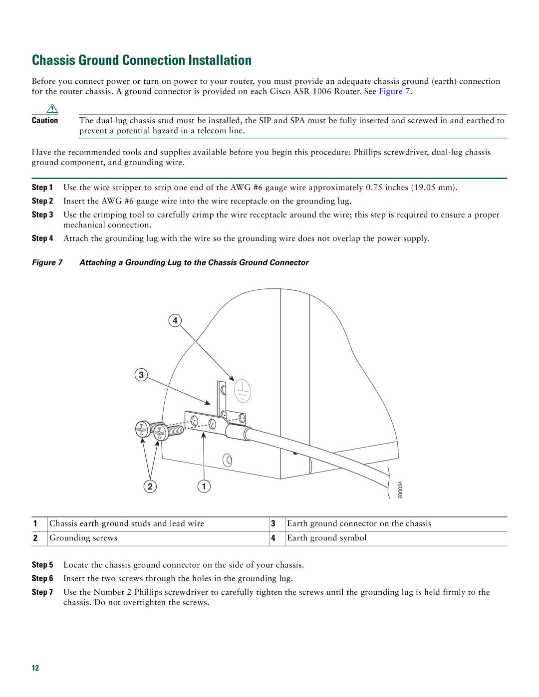
Figure 7 Attaching a Grounding Lug to the Chassis Ground Connector
4
3
2 1
![]() 280034
280034
1 | Chassis earth ground studs and lead wire | 3 | Earth ground connector on the chassis |
|
|
|
|
2 | Grounding screws | 4 | Earth ground symbol |
|
|
|
|
Step 5 Locate the chassis ground connector on the side of your chassis.
Step 6 Insert the two screws through the holes in the grounding lug.
Step 7 Use the Number 2 Phillips screwdriver to carefully tighten the screws until the grounding lug is held firmly to the chassis. Do not overtighten the screws.
12