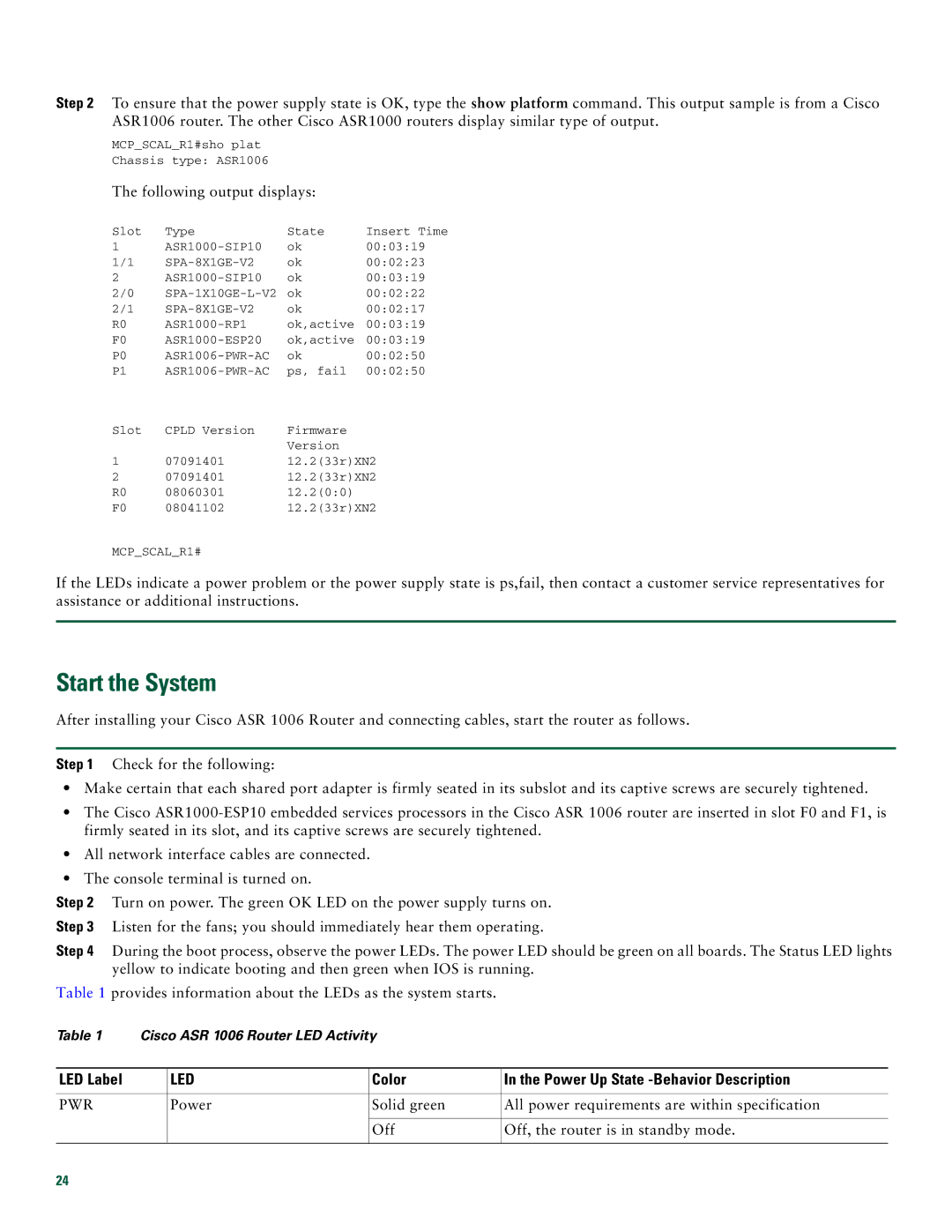
Step 2 To ensure that the power supply state is OK, type the show platform command. This output sample is from a Cisco ASR1006 router. The other Cisco ASR1000 routers display similar type of output.
MCP_SCAL_R1#sho plat
Chassis type: ASR1006
The following output displays:
Slot | Type | State | Insert Time |
1 | ok | 00:03:19 | |
1/1 | ok | 00:02:23 | |
2 | ok | 00:03:19 | |
2/0 | ok | 00:02:22 | |
2/1 | ok | 00:02:17 | |
R0 | ok,active | 00:03:19 | |
F0 | ok,active | 00:03:19 | |
P0 | ok | 00:02:50 | |
P1 | ps, fail | 00:02:50 | |
Slot | CPLD Version | Firmware |
|
|
| Version |
|
1 | 07091401 | 12.2(33r)XN2 | |
2 | 07091401 | 12.2(33r)XN2 | |
R0 | 08060301 | 12.2(0:0) |
|
F0 | 08041102 | 12.2(33r)XN2 | |
MCP_SCAL_R1#
If the LEDs indicate a power problem or the power supply state is ps,fail, then contact a customer service representatives for assistance or additional instructions.
Start the System
After installing your Cisco ASR 1006 Router and connecting cables, start the router as follows.
Step 1 Check for the following:
•Make certain that each shared port adapter is firmly seated in its subslot and its captive screws are securely tightened.
•The Cisco
•All network interface cables are connected.
•The console terminal is turned on.
Step 2 Turn on power. The green OK LED on the power supply turns on.
Step 3 Listen for the fans; you should immediately hear them operating.
Step 4 During the boot process, observe the power LEDs. The power LED should be green on all boards. The Status LED lights yellow to indicate booting and then green when IOS is running.
Table 1 provides information about the LEDs as the system starts.
Table 1 | Cisco ASR 1006 Router LED Activity |
| ||
|
|
|
|
|
LED Label |
| LED | Color | In the Power Up State |
|
|
|
|
|
PWR |
| Power | Solid green | All power requirements are within specification |
|
|
|
|
|
|
|
| Off | Off, the router is in standby mode. |
|
|
|
|
|
24
