–Connect to the port using the
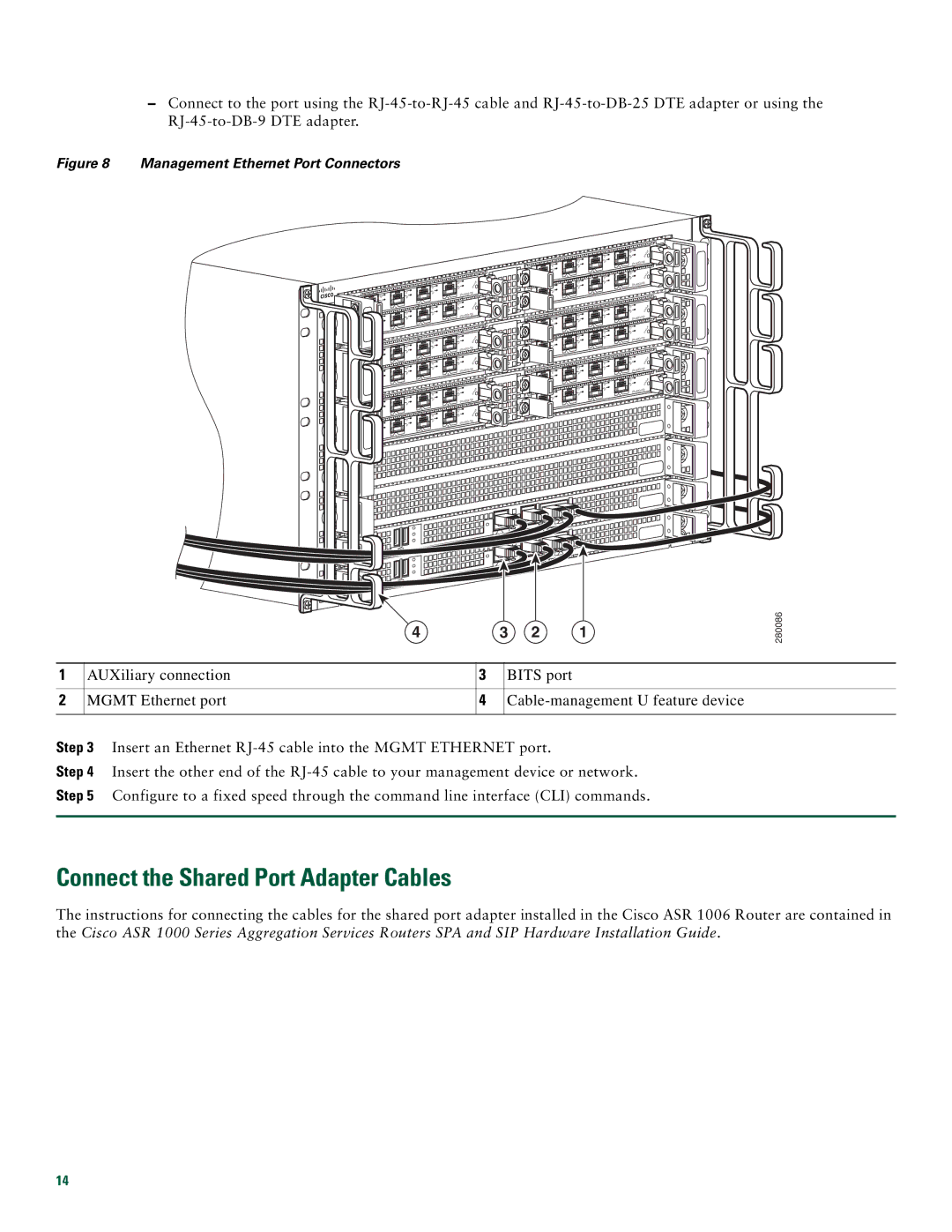
Figure 8 Management Ethernet Port Connectors
|
|
|
| C | /A |
|
| C | /A | A/L | |
C | /A | A | /L |
| 3 |
A | /L |
|
| 2 |
|
|
|
|
| ||
|
| 1 |
| C | /A |
0 |
| C | /A | A/L | |
C | /A | A | /L |
| 3 |
A | /L |
|
| 2 |
|
|
|
|
| ||
|
| 1 |
|
|
|
0 |
|
|
|
|
|
|
|
|
| C/A | |
|
| C | /A | A/L | |
C | /A | A | /L |
| 3 |
|
|
| |||
A | /L |
|
| 2 |
|
|
|
|
| ||
|
| 1 |
| C/A | |
0 |
| C | /A | A/L | |
C/A | A | /L |
| 3 | |
A | /L |
|
| 2 |
|
|
| 1 |
|
|
|
0 |
|
|
|
|
|
|
|
|
| C/A | |
|
| C | /A | A | /L |
C | /A | A | /L |
| 3 |
|
|
| |||
A | /L |
|
| 2 |
|
|
|
|
| ||
|
| 1 |
| C/A | |
0 |
| C | /A | A | /L |
C | /A | A | /L |
| 3 |
|
|
| |||
A | /L |
|
| 2 |
|
|
|
|
| ||
|
| 1 |
|
|
|
0 |
|
|
|
|
|
C | /A | T U | S |
|
| ||
| /L | T A |
|
A | S |
|
|
|
|
| ||
C | /A |
|
| T U | S |
|
|
|
| ||
| /L |
| S | T A |
|
A |
|
|
| ||
|
|
|
| ||
C | /A |
|
| T U | S |
|
|
|
| ||
A/L |
| S | T A |
| |
|
|
| |||
|
|
|
| ||
C | /A |
|
| TUS | |
|
|
| |||
| /L |
| S | T A |
|
A |
|
|
| ||
|
|
|
| ||
C | /A |
|
| T U | S |
A/L |
| S | T A |
| |
|
|
| |||
|
|
|
| ||
|
|
|
|
| |
C | /A |
|
| T U | S |
|
|
|
| ||
A/L |
| S | T A |
| |
|
|
| |||
|
|
|
| ||
|
|
|
|
| |
|
|
| C/A | |
|
| C | /A | /L |
|
| A | ||
C | /A | A | /L |
|
|
| |||
A | /L |
| 2 |
|
|
| 1 | C/A | |
0 |
| C | /A | /L |
|
| A | ||
C | /A | A | /L |
|
|
| |||
A/ | L |
|
|
|
|
| 2 |
| |
|
| 1 |
|
|
0 |
|
|
|
|
|
|
| C/A | |
|
| C | /A | /L |
|
| A | ||
C | /A | A | /L |
|
|
| |||
A | /L |
| 2 |
|
|
| 1 | C/A | |
0 |
| C | /A | /L |
|
| A | ||
C | /A | A | /L |
|
|
| |||
A | /L |
| 2 |
|
|
|
| ||
|
| 1 |
|
|
0 |
|
|
|
|
|
|
| C/A | |
|
| C | /A | /L |
|
| A | ||
C | /A | A | /L |
|
A/ | L |
|
|
|
|
| 2 |
| |
|
| 1 | C/A | |
0 |
| C | /A | /L |
|
| A | ||
C | /A | A/ | L |
|
|
|
| ||
A/ | L |
|
|
|
|
| 2 |
| |
|
| 1 |
|
|
0 |
|
|
|
|
C | /A | T US |
A/ | L | T A |
| S |
|
|
|
|
| ||
|
|
|
|
|
| |
3 |
|
|
|
|
|
|
C | /A |
|
|
| T U | S |
A/ | L |
| ST | A |
| |
|
|
|
|
| ||
|
|
|
|
|
| |
3 |
|
|
|
|
|
|
C | /A |
|
|
| T U | S |
A/L |
| S | T | A |
| |
|
|
|
| |||
|
|
|
|
| ||
|
|
|
|
|
| |
3 |
|
|
|
|
|
|
C | /A |
|
|
| T U | S |
A/L |
| S | T | A |
| |
|
|
|
| |||
|
|
|
|
| ||
|
|
|
|
|
| |
3 |
|
|
|
|
|
|
C | /A |
|
|
| T U | S |
|
|
|
|
| ||
A/L |
| S | T | A |
| |
|
|
|
| |||
|
|
|
|
| ||
3 |
|
|
|
|
|
|
C | /A |
|
|
| T U | S |
|
|
|
|
| ||
A/L |
| S | T | A |
| |
|
|
|
| |||
|
|
|
|
| ||
3 |
|
|
|
|
|
|
4 | 3 | 2 | 1 |
280086
1 | AUXiliary connection | 3 | BITS port |
|
|
|
|
2 | MGMT Ethernet port | 4 | |
|
|
|
|
Step 3 Insert an Ethernet
Step 4 Insert the other end of the
Step 5 Configure to a fixed speed through the command line interface (CLI) commands.
Connect the Shared Port Adapter Cables
The instructions for connecting the cables for the shared port adapter installed in the Cisco ASR 1006 Router are contained in the Cisco ASR 1000 Series Aggregation Services Routers SPA and SIP Hardware Installation Guide.
14