Warning | This equipment must be grounded. Never defeat the ground conductor or operate the equipment in the absence of | |
|
| a suitably installed ground conductor. Contact the appropriate electrical inspection authority or an electrician if |
|
| you are uncertain that suitable grounding is available. Statement 1024 |
|
|
|
|
|
|
Warning | This unit might have more than one power supply connection. All connections must be removed to | |
|
| unit. Statement 1028 |
|
| |
|
|
|
Warning | This product relies on the building’s installation for | |
|
| protective device is rated not greater than: AC power supplies 20 A and DC power supplies 40 A. Statement 1005 |
|
|
|
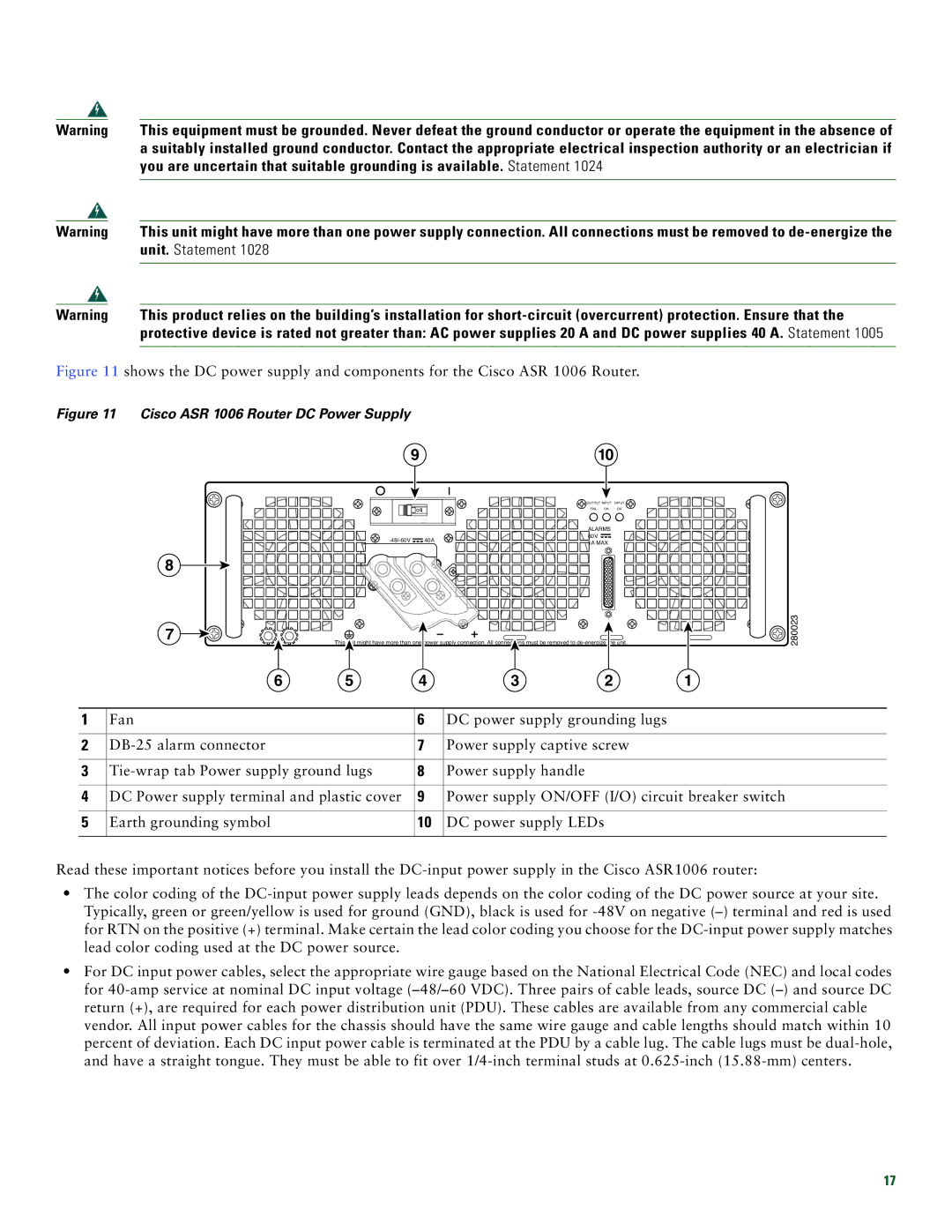
Figure 11 shows the DC power supply and components for the Cisco ASR 1006 Router.
Figure 11 Cisco ASR 1006 Router DC Power Supply
910
8
7
| OUTPUT INPUT | INPUT | |
OFF | FAIL | OK | OK |
55
|
|
| ALARMS | ||
| 40A | 60V |
|
| |
| 1A MAX | ||||
|
|
| |||
This unit might have more than one power supply connection. All connections must be removed to
6 | 5 | 4 | 3 | 2 | 1 |
![]() 280023
280023
1 | Fan | 6 | DC power supply grounding lugs |
|
|
|
|
2 | 7 | Power supply captive screw | |
|
|
|
|
3 | 8 | Power supply handle | |
|
|
|
|
4 | DC Power supply terminal and plastic cover | 9 | Power supply ON/OFF (I/O) circuit breaker switch |
|
|
|
|
5 | Earth grounding symbol | 10 | DC power supply LEDs |
|
|
|
|
Read these important notices before you install the
•The color coding of the
•For DC input power cables, select the appropriate wire gauge based on the National Electrical Code (NEC) and local codes for
17