Note DC input power cables must be connected to the PDU terminal studs in the proper positive (+) and negative
(+) lead and the negative
•An earth ground cable is required for each DC PDU. We recommend that you use at least
–
–
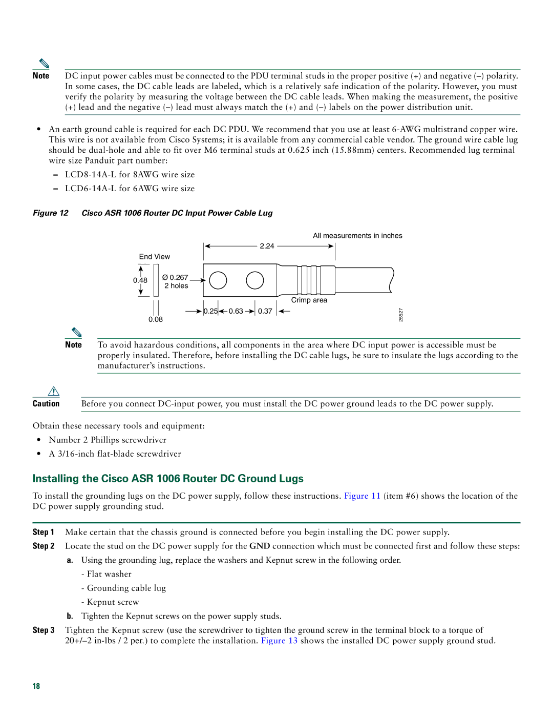
Figure 12 Cisco ASR 1006 Router DC Input Power Cable Lug
2.24
End View
|
|
|
|
| Ø 0.267 |
|
|
|
|
| |
0.48 |
| ||||
|
| 2 holes | |||
|
|
|
|
| |
|
|
|
|
|
|
![]()
![]()
![]()
![]() 0.25
0.25![]()
![]() 0.63
0.63 ![]()
![]() 0.37 0.08
0.37 0.08
All measurements in inches
Crimp area
25527
Note To avoid hazardous conditions, all components in the area where DC input power is accessible must be properly insulated. Therefore, before installing the DC cable lugs, be sure to insulate the lugs according to the manufacturer’s instructions.
Caution Before you connect
Obtain these necessary tools and equipment:
•Number 2 Phillips screwdriver
•A
Installing the Cisco ASR 1006 Router DC Ground Lugs
To install the grounding lugs on the DC power supply, follow these instructions. Figure 11 (item #6) shows the location of the DC power supply grounding stud.
Step 1 Make certain that the chassis ground is connected before you begin installing the DC power supply.
Step 2 Locate the stud on the DC power supply for the GND connection which must be connected first and follow these steps:
a.Using the grounding lug, replace the washers and Kepnut screw in the following order.
-Flat washer
-Grounding cable lug
-Kepnut screw
b.Tighten the Kepnut screws on the power supply studs.
Step 3 Tighten the Kepnut screw (use the screwdriver to tighten the ground screw in the terminal block to a torque of
18