Chapter 2 Getting Started
Installing the Cisco Video Surveillance 2630 IP Dome
To connect a power cable, use a
Step 11 (Optional) Connect an external speaker, microphone, or both to the Y cable, then connect the Y cable to the audio port on the IP dome.(see Figure
Each device connects to the audio cable through a standard 3.5 mm mini phone jack. A speaker connects to the green jack, which is labeled “Audio Out.” A microphone connects to the pink jack, which is labeled “Audio In.”
Step 12 (Optional) Use the GPIO ports to connect external devices that trigger alarms (connect through alarm input ports) or respond to alarms (connect through alarm output ports).
See Figure 1-1 on page 1-3.
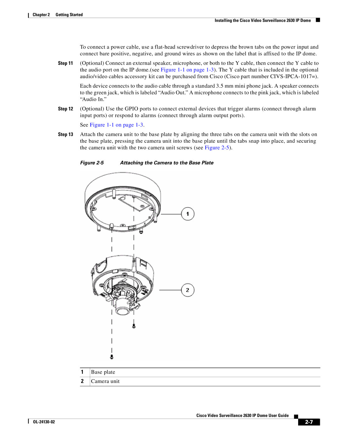
Step 13 Attach the camera unit to the base plate by aligning the three tabs on the camera unit with the slots on the base plate, pressing the camera unit into the base plate until the tabs snap into place, and securing the camera unit with the two camera unit screws (see Figure
Figure 2-5 Attaching the Camera to the Base Plate
1
2
Base plate
Camera unit
Cisco Video Surveillance 2630 IP Dome User Guide
|
| ||
|
|
