4.9 Memory Switch Setting
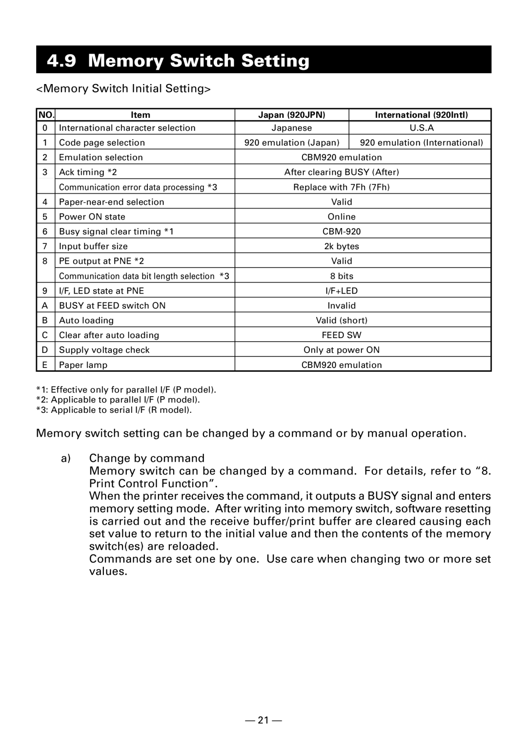
<Memory Switch Initial Setting>
NO. | Item | Japan (920JPN) |
| International (920Intl) |
0 | International character selection | Japanese |
| U.S.A |
1 | Code page selection | 920 emulation (Japan) |
| 920 emulation (International) |
2 | Emulation selection | CBM920 emulation | ||
3 | Ack timing *2 | After clearing BUSY (After) | ||
| Communication error data processing *3 | Replace with 7Fh (7Fh) | ||
4 | Valid |
| ||
5 | Power ON state | Online |
| |
6 | Busy signal clear timing *1 | |||
7 | Input buffer size | 2k bytes |
| |
8 | PE output at PNE *2 | Valid |
| |
| Communication data bit length selection *3 | 8 bits |
| |
9 | I/F, LED state at PNE | I/F+LED |
| |
A | BUSY at FEED switch ON | Invalid |
| |
B | Auto loading | Valid (short) | ||
C | Clear after auto loading | FEED SW | ||
D | Supply voltage check | Only at power ON | ||
E | Paper lamp | CBM920 emulation | ||
*1: Effective only for parallel I/F (P model).
*2: Applicable to parallel I/F (P model).
*3: Applicable to serial I/F (R model).
Memory switch setting can be changed by a command or by manual operation.
a)Change by command
Memory switch can be changed by a command. For details, refer to “8. Print Control Function”.
When the printer receives the command, it outputs a BUSY signal and enters memory setting mode. After writing into memory switch, software resetting is carried out and the receive buffer/print buffer are cleared causing each set value to return to the initial value and then the contents of the memory switch(es) are reloaded.
Commands are set one by one. Use care when changing two or more set values.
— 21 —