5.PARALLEL INTERFACE
5.1Specifications
(1)Data input system: 8 bit parallel (DATA
(2)Control signal: ACK, STB, BUSY, PE, RESET, FAULT
(3)Power cable: +5V, GND and FG
(4)Compatible connector:
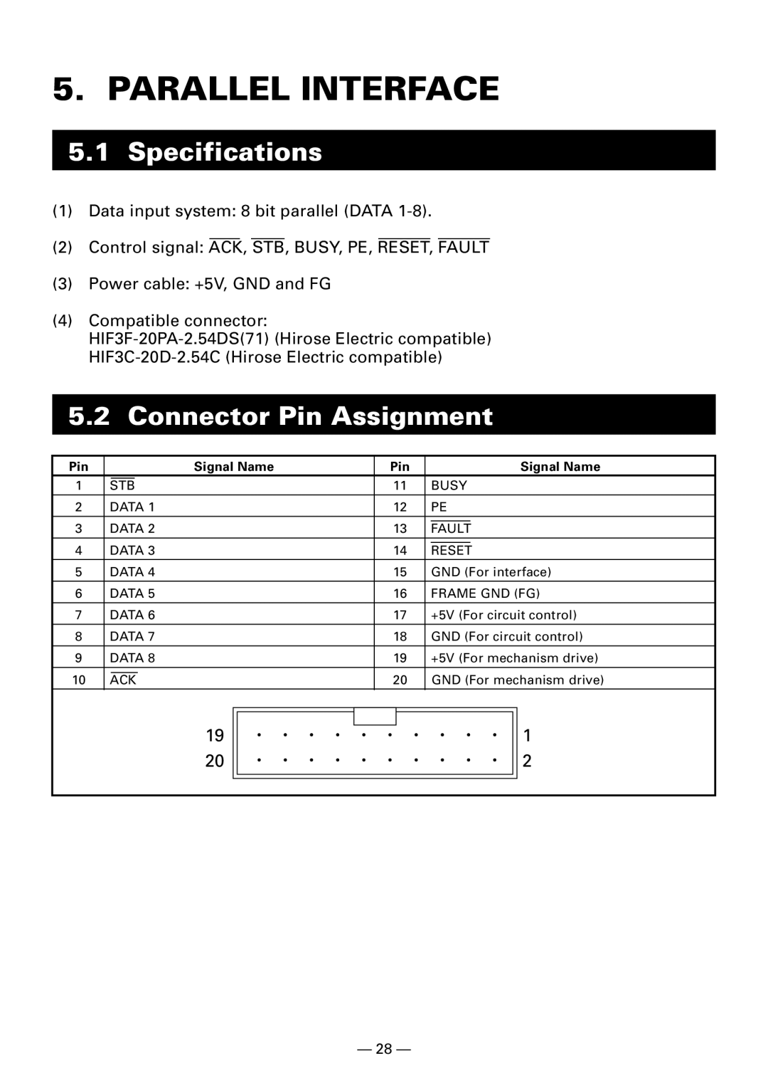
5.2Connector Pin Assignment
Pin |
|
|
| Signal Name | Pin |
|
| Signal Name | ||
1 |
|
|
| 11 |
| BUSY | ||||
| STB |
|
|
|
| |||||
2 | DATA 1 | 12 |
| PE | ||||||
3 | DATA 2 | 13 |
|
| ||||||
| FAULT |
| ||||||||
4 | DATA 3 | 14 |
|
| ||||||
| RESET |
| ||||||||
5 | DATA 4 | 15 |
| GND (For interface) | ||||||
6 | DATA 5 | 16 |
| FRAME GND (FG) | ||||||
7 | DATA 6 | 17 |
| +5V (For circuit control) | ||||||
8 | DATA 7 | 18 |
| GND (For circuit control) | ||||||
9 | DATA 8 | 19 |
| +5V (For mechanism drive) | ||||||
10 |
|
|
|
| 20 |
| GND (For mechanism drive) | |||
ACK | ||||||||||
|
|
|
|
|
|
|
|
|
|
|
|
|
|
|
|
|
|
|
|
|
|
19 | 1 |
20 | 2 |
— 28 —