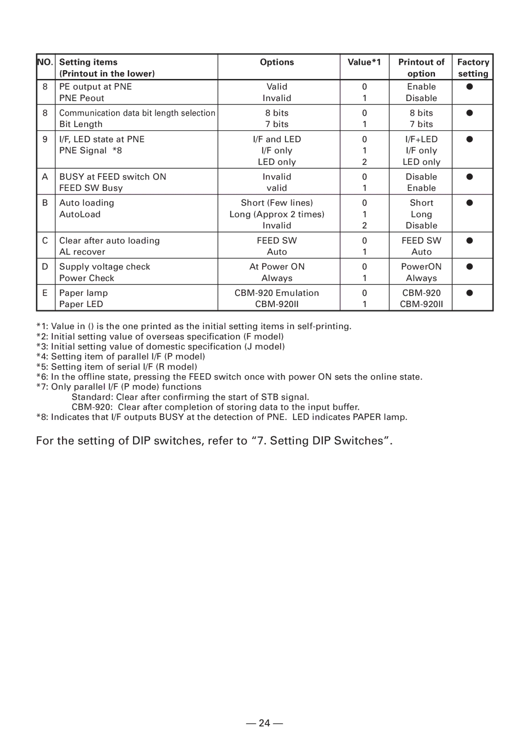
NO. | Setting items | Options | Value*1 | Printout of | Factory |
| (Printout in the lower) |
|
| option | setting |
8 | PE output at PNE | Valid | 0 | Enable | ● |
| PNE Peout | Invalid | 1 | Disable |
|
8 | Communication data bit length selection | 8 bits | 0 | 8 bits | ● |
| Bit Length | 7 bits | 1 | 7 bits |
|
9 | I/F, LED state at PNE | I/F and LED | 0 | I/F+LED | ● |
| PNE Signal *8 | I/F only | 1 | I/F only |
|
|
| LED only | 2 | LED only |
|
A | BUSY at FEED switch ON | Invalid | 0 | Disable | ● |
| FEED SW Busy | valid | 1 | Enable |
|
B | Auto loading | Short (Few lines) | 0 | Short | ● |
| AutoLoad | Long (Approx 2 times) | 1 | Long |
|
|
| Invalid | 2 | Disable |
|
C | Clear after auto loading | FEED SW | 0 | FEED SW | ● |
| AL recover | Auto | 1 | Auto |
|
D | Supply voltage check | At Power ON | 0 | PowerON | ● |
| Power Check | Always | 1 | Always |
|
E | Paper lamp | 0 | ● | ||
| Paper LED |
| 1 |
|
*1: Value in () is the one printed as the initial setting items in
*2: Initial setting value of overseas specification (F model)
*3: Initial setting value of domestic specification (J model)
*4: Setting item of parallel I/F (P model)
*5: Setting item of serial I/F (R model)
*6: In the offline state, pressing the FEED switch once with power ON sets the online state.
*7: Only parallel I/F (P mode) functions
Standard: Clear after confirming the start of STB signal.
*8: Indicates that I/F outputs BUSY at the detection of PNE. LED indicates PAPER lamp.
For the setting of DIP switches, refer to “7. Setting DIP Switches”.
— 24 —