6.3Description of Input/Output Signal
(1)Signal input to printer
RxD(RECEIVE DATA) . . . Serial receive data signal
(2)Signal input to printer (TTL,CMOS)
RESET. . . Signal for resetting the whole printer (negative logic) 4 ms or more
(3)Signal output from printer
DTR(DATA TERMINAL READY)
When this signal is Ready (Space), send data or command from the host. If transmission is made when this signal is Busy (Mark), overrun error occurs. If the signal is ready even if the printer is in printing operation, data can be sent to the input buffer.
At the time of printer power on, test printing, reset occurrence, and memory switch setting, this signal is Busy.
(4)Signal output from printer (TTL,CMOS)
PE. . . Signal indicating end of paper (positive logic)
FAULT. . . Signal indicating occurrence of failure such as mechanism alarm (negative logic)
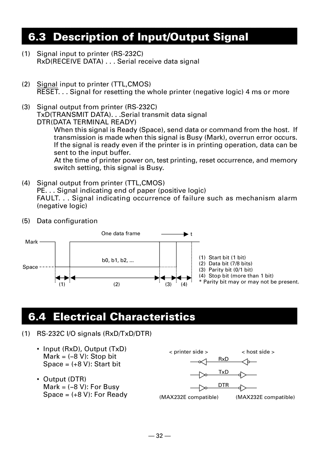
(5) Data configuration
Mark |
|
|
|
|
|
| One data frame |
|
|
|
|
| t | |
|
|
|
|
|
|
|
|
| ||||||
|
|
|
|
|
| b0, b1, b2, ... |
|
|
|
|
|
| ||
|
|
|
|
|
|
|
|
| ||||||
|
|
|
|
|
|
|
|
|
|
|
|
| ||
Space |
|
|
|
|
|
|
|
|
|
|
|
|
| |
|
|
|
|
|
|
|
|
|
|
|
|
| ||
|
|
|
|
|
|
|
|
|
| |||||
(1) | (2) |
| (3) | (4) | ||||||||||
(1)Start bit (1 bit)
(2)Data bit (7/8 bits)
(3)Parity bit (0/1 bit)
(4)Stop bit (more than 1 bit)
* Parity bit may or may not be present.
6.4 Electrical Characteristics
(1)
•Input (RxD), Output (TxD) Mark = (−8 V): Stop bit Space = (+8 V): Start bit
•Output (DTR)
Mark = (−8 V): For Busy
Space = (+8 V): For Ready
< printer side > | < host side > |
RxD |
|
TxD |
|
DTR |
|
(MAX232E compatible) | (MAX232E compatible) |
— 32 —