2.For 40-column model
In
With ESC (1BH) + ”&” (26H) + {C1} + A1 + A2 code and the pattern data following input, a pattern is registered. Only
[Recognition of use of upper most bit]
For recognition of use or
C1=0 (00H): Uppermost bit not used.
Other than C1=0: Uppermost bit used.
If 0 is set to this parameter regardless of whether most significant bit is specified, character as imaged cannot be registered.
[Setting of addresses]
A1 : Registration starting address (20H~FFH)
A2 : Registration ending address (20H~FFH)
[Pattern data configuration]
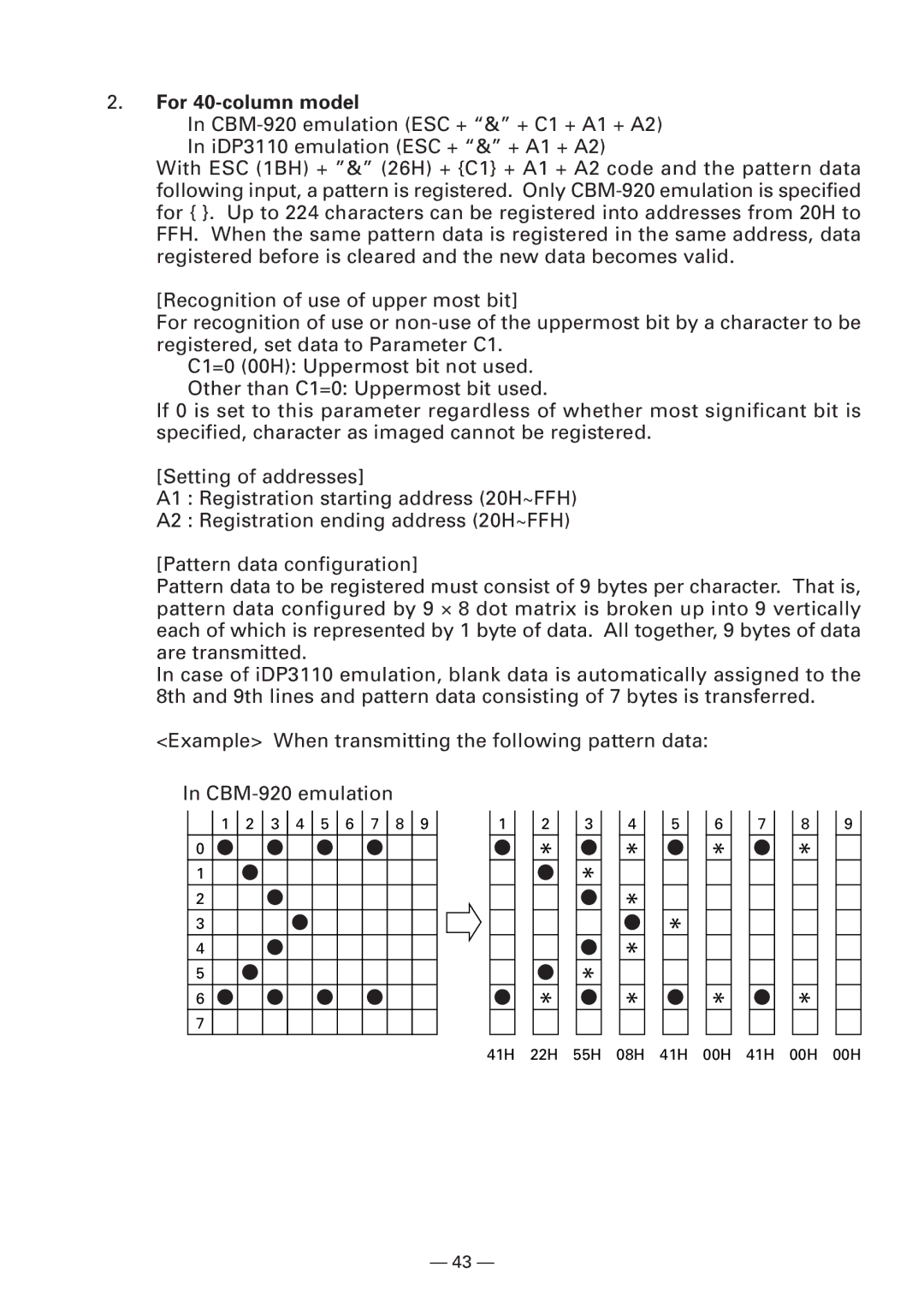
Pattern data to be registered must consist of 9 bytes per character. That is, pattern data configured by 9 ⋅ 8 dot matrix is broken up into 9 vertically each of which is represented by 1 byte of data. All together, 9 bytes of data are transmitted.
In case of iDP3110 emulation, blank data is automatically assigned to the 8th and 9th lines and pattern data consisting of 7 bytes is transferred.
<Example> When transmitting the following pattern data:
In
1 2 3 4 5 6 7 8 9
0
1
2
3
4
5
6
7
1
2
*
*
3
*
*
4
*
*
*
*
5
*
6
*
*
7
8
*
*
9
41H 22H 55H 08H 41H 00H 41H 00H 00H
— 43 —
