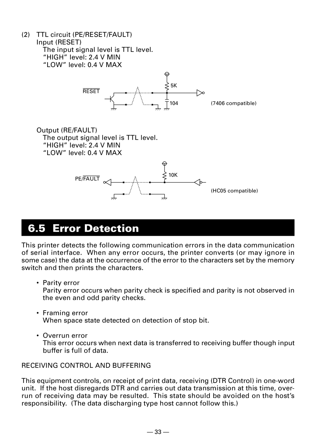
(2)TTL circuit (PE/RESET/FAULT) Input (RESET)
The input signal level is TTL level. “HIGH” level: 2.4 V MIN “LOW” level: 0.4 V MAX
5K
RESET
|
| 104 | (7406 compatible) | |
| ||||
|
|
|
|
|
Output (RE/FAULT)
The output signal level is TTL level. “HIGH” level: 2.4 V MIN
“LOW” level: 0.4 V MAX
PE/FAULT
10K
(HC05 compatible)
6.5 Error Detection
This printer detects the following communication errors in the data communication of serial interface. When any error occurs, the printer converts (or may ignore in some case) the data at the occurrence of the error to the characters set by the memory switch and then prints the characters.
•Parity error
Parity error occurs when parity check is specified and parity is not observed in the even and odd parity checks.
•Framing error
When space state detected on detection of stop bit.
•Overrun error
This error occurs when next data is transferred to receiving buffer though input buffer is full of data.
RECEIVING CONTROL AND BUFFERING
This equipment controls, on receipt of print data, receiving (DTR Control) in
— 33 —