PRELIMINARY CY8CNP102B, CY8CNP102E
Online Help System
The online help system displays online, context sensitive help for the user. Designed for procedural and quick reference, each functional subsystem has its own context sensitive help. This system also provides tutorials and links to FAQs and an Online Support Forum to aid the designer in getting started.
Hardware Tools
In-Circuit Emulator
A low cost, high functionality ICE
The emulator consists of a base unit that connects to the PC through the USB port. The base unit is universal and operates with all PSoC devices. Emulation pods for each device family are available separately. The emulation pod takes the place of the PSoC device in the target board and performs full speed
(24 MHz) operation.
Designing with User Modules
The development process for the PSoC device differs from that of a traditional fixed function microprocessor. The configurable analog and digital hardware blocks give the PSoC architecture a unique flexibility that manages specification change during development and lowers inventory costs. These configurable resources, called PSoC Blocks, implement a wide variety of
To speed the development process, the PSoC Designer IDE provides a library of prebuilt, pretested hardware peripheral functions, called “User Modules.” User modules simplify selecting and implementing peripheral devices, and come in analog, digital, and mixed signal varieties. The standard User Module library contains over 50 peripherals such as ADCs, DACs, Timers, Counters, UARTs, nvSRAM, DTMF Generators, and
Each user module establishes the basic register settings that implement the selected function. It also provides parameters that enable you to tailor its precise configuration to your particular application. For example, a Pulse Width Modulator User Module configures one or more digital PSoC blocks, one for each 8 bits of resolution. The user module parameters permit you to establish the pulse width and duty cycle. User modules also provide tested software to cut your development time. The user module Application Programming Interface (API) provides high level functions to control and respond to hardware events at run time. The API also provides optional interrupt service routines that you can adapt as needed.
The API functions are documented in user module data sheets that are viewed directly in the PSoC Designer IDE. These data sheets explain the internal operation of the user module and provide performance specifications. Each data sheet describes the use of each user module parameter and documents the setting of each register controlled by the user module.
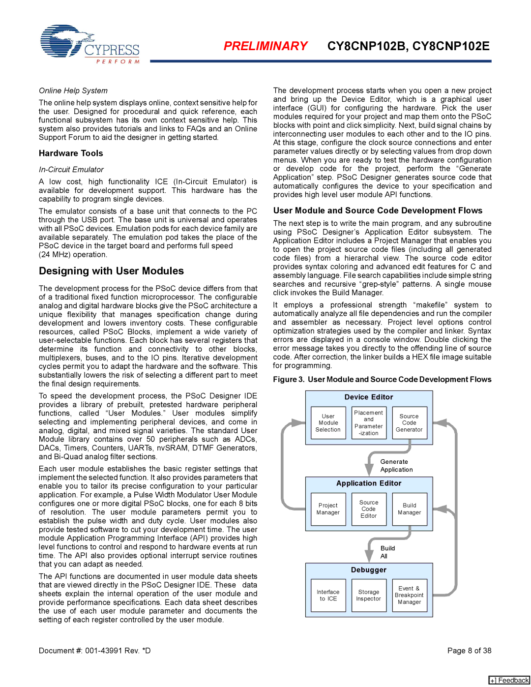
The development process starts when you open a new project and bring up the Device Editor, which is a graphical user interface (GUI) for configuring the hardware. Pick the user modules required for your project and map them onto the PSoC blocks with point and click simplicity. Next, build signal chains by interconnecting user modules to each other and to the IO pins. At this stage, configure the clock source connections and enter parameter values directly or by selecting values from drop down menus. When you are ready to test the hardware configuration or develop code for the project, perform the “Generate Application” step. PSoC Designer generates source code that automatically configures the device to your specification and provides high level user module API functions.
User Module and Source Code Development Flows
The next step is to write the main program, and any subroutine using PSoC Designer’s Application Editor subsystem. The Application Editor includes a Project Manager that enables you to open the project source code files (including all generated code files) from a hierarchal view. The source code editor provides syntax coloring and advanced edit features for C and assembly language. File search capabilities include simple string searches and recursive
It employs a professional strength “makefile” system to automatically analyze all file dependencies and run the compiler and assembler as necessary. Project level options control optimization strategies used by the compiler and linker. Syntax errors are displayed in a console window. Double clicking the error message takes you directly to the offending line of source code. After correction, the linker builds a HEX file image suitable for programming.
Figure 3. User Module and Source Code Development Flows
|
|
| Device Editor |
|
|
|
|
|
| |||||
|
|
|
|
|
|
|
|
|
|
|
|
|
|
|
|
| User |
|
| Placement |
|
| Source |
|
| ||||
|
|
|
| and |
|
|
|
| ||||||
|
| Module |
|
|
|
| Code |
|
| |||||
|
|
|
| Parameter |
|
|
|
| ||||||
|
| Selection |
|
|
|
| Generator |
|
| |||||
|
|
|
|
|
|
|
| |||||||
|
|
|
|
|
|
|
|
|
|
|
|
| ||
|
|
|
|
|
|
|
|
|
|
|
|
|
|
|
|
|
|
|
|
|
|
|
|
|
|
|
|
|
|
|
|
|
|
|
|
|
|
|
|
|
|
|
|
|
Generate
Application
Application Editor
Project |
| Source |
| Build | ||||
| Code |
| ||||||
Manager |
|
| Manager | |||||
| Editor |
| ||||||
|
|
|
|
|
|
| ||
|
|
|
|
|
|
|
|
|
|
|
|
|
|
|
|
|
|
|
|
|
|
|
|
|
|
|
|
|
|
|
| Build |
| |||
|
|
|
|
| All |
|
|
| |
|
|
|
|
|
|
|
|
|
|
|
| Debugger |
|
|
| ||||
|
|
|
|
|
|
|
|
|
|
| Interface |
| Storage |
| Event & |
|
| ||
|
|
| Breakpoint |
|
| ||||
| to ICE |
| Inspector |
|
|
| |||
|
|
|
|
| |||||
|
|
| Manager |
|
| ||||
|
|
|
|
|
|
|
|
| |
|
|
|
|
|
|
|
|
|
|
|
|
|
|
|
|
|
|
|
|
Document #: | Page 8 of 38 |
[+] Feedback