Section 1 Getting Started
QUANTUM
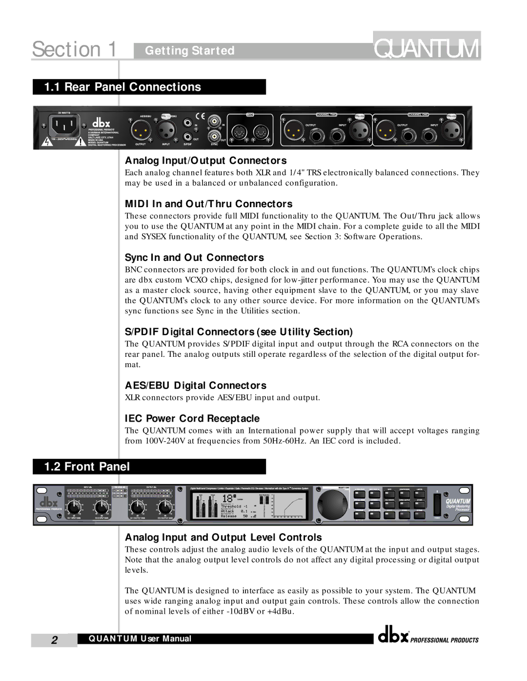
1.1 Rear Panel Connections
Analog Input/Output Connectors
Each analog channel features both XLR and 1/4" TRS electronically balanced connections. They may be used in a balanced or unbalanced configuration.
MIDI In and Out/Thru Connectors
These connectors provide full MIDI functionality to the QUANTUM. The Out/Thru jack allows you to use the QUANTUM at any point in the MIDI chain. For a complete guide to all the MIDI and SYSEX functionality of the QUANTUM, see Section 3: Software Operations.
Sync In and Out Connectors
BNC connectors are provided for both clock in and out functions. The QUANTUM’s clock chips are dbx custom VCXO chips, designed for
S/PDIF Digital Connectors (see Utility Section)
The QUANTUM provides S/PDIF digital input and output through the RCA connectors on the rear panel. The analog outputs still operate regardless of the selection of the digital output for- mat.
AES/EBU Digital Connectors
XLR connectors provide AES/EBU input and output.
IEC Power Cord Receptacle
The QUANTUM comes with an International power supply that will accept voltages ranging from
1.2 Front Panel
Analog Input and Output Level Controls
These controls adjust the analog audio levels of the QUANTUM at the input and output stages. Note that the analog output level controls do not affect any digital processing or digital output levels.
The QUANTUM is designed to interface as easily as possible to your system. The QUANTUM uses wide ranging analog input and output gain controls. These controls allow the connection of nominal levels of either
®
2 | QUANTUM User Manual |
|
|