QUANTUM
Application Guide Section 6
6.8 Analog to Digital Converter
Hardware
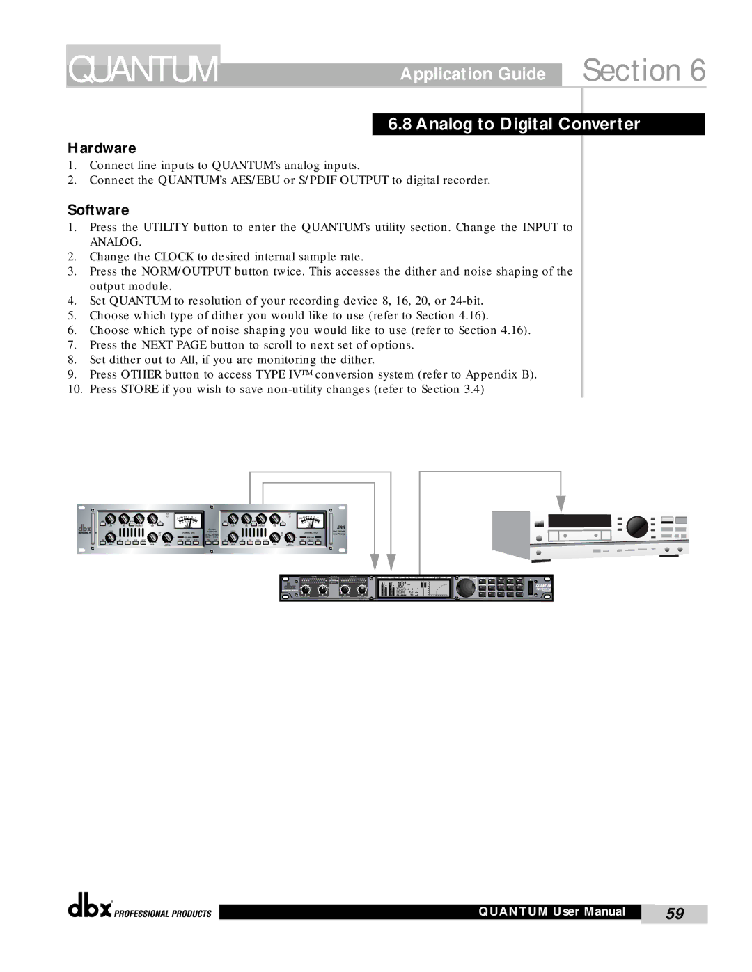
1.Connect line inputs to QUANTUM’s analog inputs.
2.Connect the QUANTUM’s AES/EBU or S/PDIF OUTPUT to digital recorder.
Software
1.Press the UTILITY button to enter the QUANTUM’s utility section. Change the INPUT to
ANALOG.
2.Change the CLOCK to desired internal sample rate.
3.Press the NORM/OUTPUT button twice. This accesses the dither and noise shaping of the output module.
4.Set QUANTUM to resolution of your recording device 8, 16, 20, or
5.Choose which type of dither you would like to use (refer to Section 4.16).
6.Choose which type of noise shaping you would like to use (refer to Section 4.16).
7.Press the NEXT PAGE button to scroll to next set of options.
8.Set dither out to All, if you are monitoring the dither.
9.Press OTHER button to access TYPE IV™ conversion system (refer to Appendix B).
10.Press STORE if you wish to save
|
|
|
|
|
| CLIP |
|
|
|
|
|
|
|
|
|
| CLIP |
|
|
|
|
|
|
|
|
| 2010 7 5 3 | 0 3 |
|
|
|
|
|
|
|
| 2010 7 5 3 | 0 3 |
| ||
INSERT |
|
| NARROW |
| EQ | - |
|
| + |
| INSERT |
|
| NARROW |
| EQ | - |
|
| + |
dB |
| dB |
| dB | dB |
|
|
|
|
| dB |
| dB |
| dB | dB |
|
|
| 586 |
LOW |
| MID | FREQUENCY | HIGH |
|
|
|
|
| LOW |
| MID | FREQUENCY | HIGH |
|
|
| |||
|
|
|
|
|
|
|
|
|
| TYPE IV |
|
|
|
|
|
|
|
|
| |
|
|
|
|
| LIMIT |
| CHANNEL ONE | CONVERSION SYSTEM |
|
|
|
|
| LIMIT | CHANNEL TWO | Dual Vacuum | ||||
|
|
|
|
|
| Red: SNR | Red: Shape 2 |
|
|
|
|
| Tube Preamp | |||||||
|
|
|
|
|
|
| METER SOURCE | Green: TPDF Green: Shape 1 |
|
|
|
|
|
|
| METER SOURCE |
| |||
|
|
|
|
|
|
| Off: None | Off: None |
|
|
|
|
|
|
|
| ||||
LINE | +48V | PAD | PHASE | LOW CUT |
| DRIVE | INSERT | OUTPUT | DITHER | SHAPE | LINE | +48V | PAD | PHASE | LOW CUT |
| DRIVE | INSERT | OUTPUT |
|
dB |
|
|
|
| dB | dB |
|
|
|
| dB |
|
|
|
| dB | dB |
|
|
|
DRIVE |
|
|
|
| LEVEL | PeakPlus |
|
|
|
| DRIVE |
|
|
|
| LEVEL | PeakPlus |
|
|
|
|
|
|
|
|
| THRESHOLD |
|
|
|
|
|
|
|
|
|
| THRESHOLD |
|
|
|
®
QUANTUM User Manual | 59 |
|
|