QUANTUM
Application Guide Section 6
6.4 Analog Tracking
Hardware
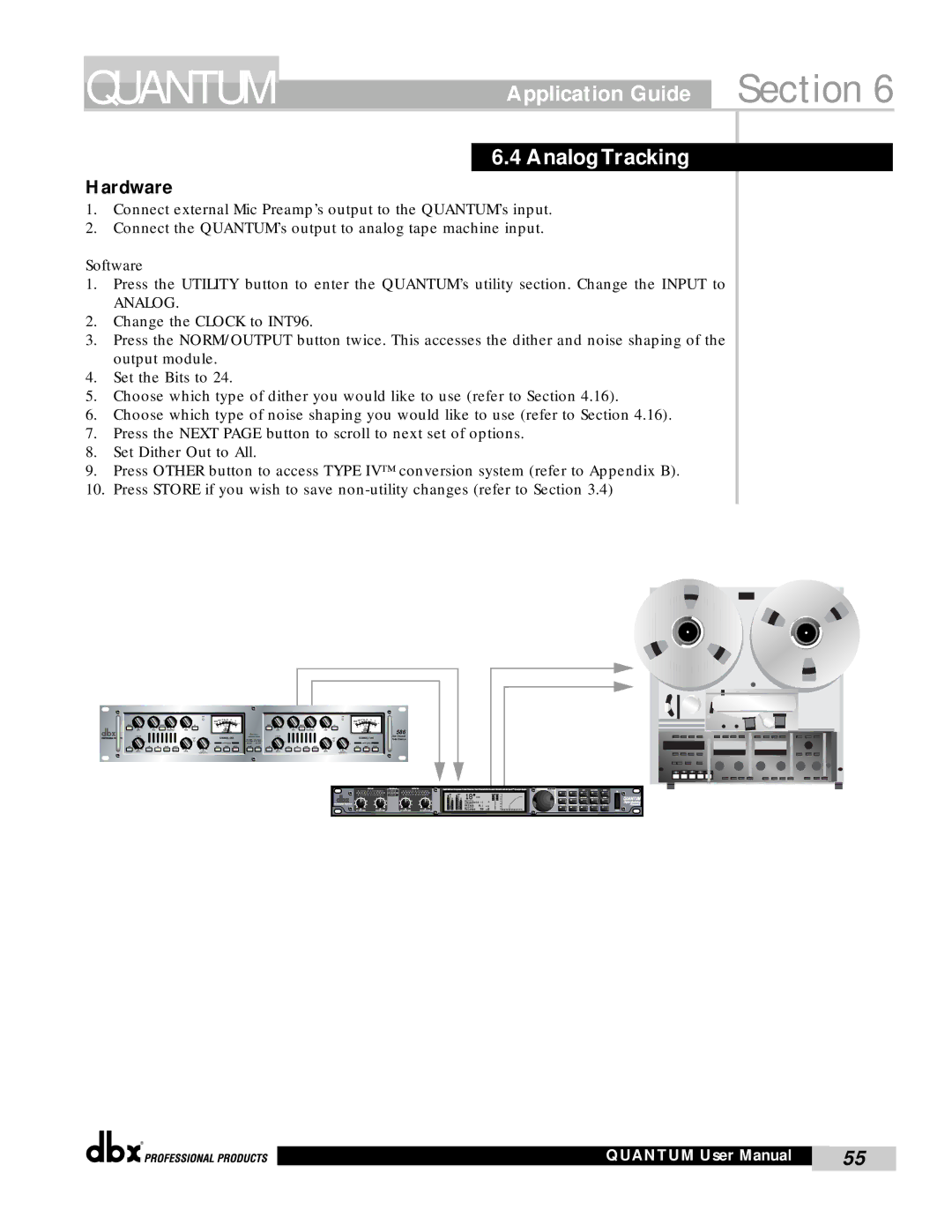
1.Connect external Mic Preamp’s output to the QUANTUM’s input.
2.Connect the QUANTUM’s output to analog tape machine input.
Software
1.Press the UTILITY button to enter the QUANTUM’s utility section. Change the INPUT to
ANALOG.
2.Change the CLOCK to INT96.
3.Press the NORM/OUTPUT button twice. This accesses the dither and noise shaping of the output module.
4.Set the Bits to 24.
5.Choose which type of dither you would like to use (refer to Section 4.16).
6.Choose which type of noise shaping you would like to use (refer to Section 4.16).
7.Press the NEXT PAGE button to scroll to next set of options.
8.Set Dither Out to All.
9.Press OTHER button to access TYPE IV™ conversion system (refer to Appendix B).
10.Press STORE if you wish to save
|
|
|
|
|
| CLIP |
|
|
|
|
|
|
|
|
|
| CLIP |
|
|
|
|
|
|
|
|
| 2010 7 5 3 | 0 3 |
|
|
|
|
|
|
|
| 2010 7 5 3 | 0 3 |
| ||
INSERT |
|
| NARROW |
| EQ | - |
|
| + |
| INSERT |
|
| NARROW |
| EQ | - |
|
| + |
dB |
| dB |
| dB | dB |
|
|
|
| TYPE IV | dB |
| dB |
| dB | dB |
|
|
| 586 |
LOW |
| MID | FREQUENCY | HIGH |
|
|
|
|
| LOW |
| MID | FREQUENCY | HIGH |
|
|
|
| ||
|
|
|
|
| LIMIT |
| CHANNEL ONE | CONVERSION SYSTEM |
|
|
|
|
| LIMIT | CHANNEL TWO | Dual Vacuum | ||||
|
|
|
|
|
|
|
|
|
|
|
|
| Tube Preamp | |||||||
|
|
|
|
|
|
| METER SOURCE |
|
|
|
|
|
|
|
|
| METER SOURCE |
| ||
LINE | +48V | PAD | PHASE | LOW CUT |
| DRIVE | INSERT | OUTPUT | DITHER | SHAPE | LINE | +48V | PAD | PHASE | LOW CUT |
| DRIVE | INSERT | OUTPUT |
|
dB |
|
|
|
| dB | dB |
|
|
|
| dB |
|
|
|
| dB | dB |
|
|
|
DRIVE |
|
|
|
| LEVEL | PeakPlus |
|
|
|
| DRIVE |
|
|
|
| LEVEL | PeakPlus |
|
|
|
|
|
|
|
|
| THRESHOLD |
|
|
|
|
|
|
|
|
|
| THRESHOLD |
|
|
|
®
QUANTUM User Manual | 55 |
|
|