QUANTUM
Software Operations Section 3
3.6 Meters (cont.)
Digital Meters
The middle portion of the meter represents the peak level of the signal. The sides of the meter represent the average peak level. Since the digital output meter is located after dither, changes made to dither will be seen at this meter. Digital clipping is represented by a large “C” at the top of the meter.
Peak
Shoulder ![]()
![]()
![]()
![]()
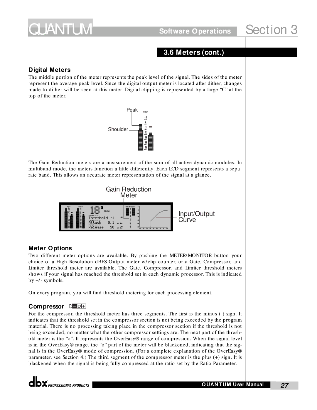
The Gain Reduction meters are a measurement of the sum of all active dynamic modules. In multiband mode, the meters function a little differently. Each LCD segment represents a sepa- rate band. This allows an accurate meter representation of the signal at a glance.
Gain Reduction
Meter
Input/Output
Curve
Meter Options
Two different meter options are available. By pushing the METER/MONITOR button your choice of a High Resolution dBFS Output meter w/clip counter, or a Gate, Compressor, and Limiter threshold meter are available. The Gate, Compressor, and Limiter threshold meters shows if your signal has reached the threshold set in each dynamic processor. This is indicated by +/- symbols.
On every program, you will find threshold metering for each processing element.
Compressor
For the compressor, the threshold meter has three segments. The first is the minus
®
QUANTUM User Manual | 27 |
|
|
