1Follow the procedures in "Before You Begin" on page 101.
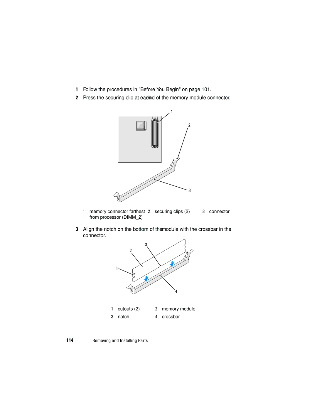
2Press the securing clip at each end of the memory module connector.
1
2
| 3 |
1 memory connector farthest 2 securing clips (2) | 3 connector |
from processor (DIMM_2) |
|
3Align the notch on the bottom of the module with the crossbar in the connector.
3
| 2 |
|
|
| 1 |
|
|
|
|
| 4 |
1 | cutouts (2) | 2 | memory module |
3 | notch | 4 | crossbar |
