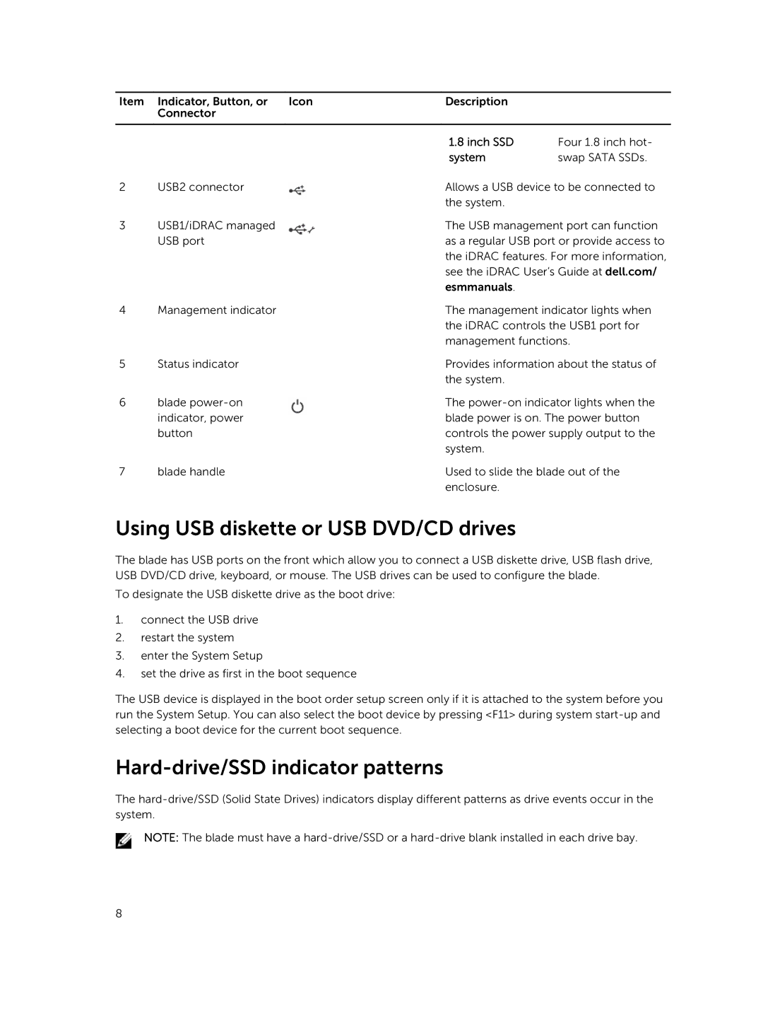
Item | Indicator, Button, or Icon | Description |
|
| Connector |
|
|
|
|
|
|
|
| 1.8 inch SSD | Four 1.8 inch hot- |
|
| system | swap SATA SSDs. |
2 | USB2 connector | Allows a USB device to be connected to | |
|
| the system. |
|
3 | USB1/iDRAC managed | The USB management port can function | |
| USB port | as a regular USB port or provide access to | |
|
| the iDRAC features. For more information, | |
|
| see the iDRAC User’s Guide at dell.com/ | |
|
| esmmanuals. |
|
4 | Management indicator | The management indicator lights when | |
|
| the iDRAC controls the USB1 port for | |
|
| management functions. | |
5 | Status indicator | Provides information about the status of | |
|
| the system. |
|
6 | blade | The | |
| indicator, power | blade power is on. The power button | |
| button | controls the power supply output to the | |
|
| system. |
|
7 | blade handle | Used to slide the blade out of the | |
|
| enclosure. |
|
Using USB diskette or USB DVD/CD drives
The blade has USB ports on the front which allow you to connect a USB diskette drive, USB flash drive, USB DVD/CD drive, keyboard, or mouse. The USB drives can be used to configure the blade.
To designate the USB diskette drive as the boot drive:
1.connect the USB drive
2.restart the system
3.enter the System Setup
4.set the drive as first in the boot sequence
The USB device is displayed in the boot order setup screen only if it is attached to the system before you run the System Setup. You can also select the boot device by pressing <F11> during system
Hard-drive/SSD indicator patterns
The
NOTE: The blade must have a
8
