Brick Motion Controller Hardware Reference Manual
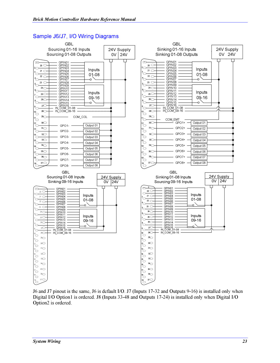
Sample J6/J7, I/O Wiring Diagrams
|
| GBL |
|
| |
|
| Sourcing | 24V Supply | ||
|
| Sourcing | 0V | 24V | |
1 |
| GPIN01 |
|
|
|
|
|
|
|
| |
| 20 | GPIN02 |
|
|
|
2 |
| GPIN03 | Inputs |
|
|
3 | 21 | GPIN04 |
|
| |
| 22 | GPIN05 |
|
| |
4 |
| GPIN06 |
|
|
|
| GPIN07 |
|
|
| |
|
|
|
|
| |
5 | 23 | GPIN08 |
|
|
|
| GPIN09 |
|
|
| |
|
|
|
|
| |
6 | 24 | GPIN10 |
|
|
|
| GPIN11 | Inputs |
|
| |
7 | 25 | GPIN12 |
|
| |
|
| GPIN13 |
|
|
|
8 | 26 | GPIN14 |
|
| |
|
| GPIN15 |
|
|
|
9 | 27 | GPIN16 |
|
|
|
|
|
|
| ||
10 | 28 |
|
| ||
11 | 29 |
| COM_COL |
|
|
|
|
|
| ||
12 | 30 | GPO1- | Output 01 |
|
|
| 31 |
|
| ||
13 | GPO2- | Output 02 |
|
| |
|
|
| |||
| 32 |
|
| ||
14 | GPO3- | Output 03 |
|
| |
| 33 |
|
| ||
15 | GPO4- | Output 04 |
|
| |
|
|
| |||
| 34 |
|
| ||
16 |
|
|
|
| |
| GPO5- | Output 05 |
|
| |
| 35 |
|
| ||
17 | GPO6- | Output 06 |
|
| |
|
|
| |||
| 36 |
|
| ||
18 | GPO7- | Output 07 |
|
| |
|
|
| |||
| 37 |
|
| ||
19 | GPO8- | Output 08 |
|
| |
|
|
|
| ||
|
| GBL |
| 24V Supply | |
|
| Sinking | |||
|
| Sinking | 0V | 24V | |
1 |
| GPIN01 |
|
|
|
| 20 | GPIN02 |
|
|
|
2 | 21 | GPIN03 | Inputs |
|
|
3 | GPIN04 |
|
| ||
4 | 22 | GPIN05 |
|
| |
| GPIN06 |
|
|
| |
|
| GPIN07 |
|
|
|
5 | 23 | GPIN08 |
|
|
|
| GPIN09 |
|
|
| |
|
|
|
|
| |
6 | 24 | GPIN10 |
|
|
|
| GPIN11 | Inputs |
|
| |
|
|
|
| ||
7 | 25 | GPIN12 |
|
| |
|
| GPIN13 |
|
| |
8 | 26 | GPIN14 |
|
| |
|
| GPIN15 |
|
|
|
9 | 27 | GPIN16 |
|
|
|
|
|
|
|
| |
10 | 28 |
|
|
| |
11 | 29 | COM_EMT |
|
|
|
|
|
|
| ||
|
|
|
|
| |
12 | 30 | GPO1+ | Output 01 |
|
|
13 | 31 | GPO2+ | Output 02 |
|
|
14 | 32 | GPO3+ | Output 03 |
|
|
15 | 33 | GPO4+ | Output 04 |
|
|
16 | 34 | GPO5+ | Output 05 |
|
|
17 | 35 | GPO6+ | Output 06 |
|
|
18 | 36 | GPO7+ | Output 07 |
|
|
19 | 37 | GPO8+ | Output 08 |
|
|
GBL |
|
|
Sourcing | 24V Supply | |
Sinking | 0V 24V | |
|
|
|
GBL
Sinking
Sourcing
24V Supply
0V 24V
1 |
| GPIN01 |
|
| 20 | GPIN02 |
|
2 |
| GPIN03 | Inputs |
3 | 21 | GPIN04 | |
| 22 | GPIN05 | |
4 |
| GPIN06 |
|
| GPIN07 |
| |
|
|
| |
5 | 23 | GPIN08 |
|
| GPIN09 |
| |
| 24 |
| |
6 | GPIN10 |
| |
| GPIN11 | Inputs | |
7 | 25 | GPIN12 | |
| 26 | GPIN13 |
|
8 | GPIN14 | ||
|
| GPIN15 |
|
9 | 27 | GPIN16 |
|
|
|
| |
10 | 28 |
|
1 | 2 |
| 20 |
3 | 21 |
| |
4 | 22 |
| |
5 | 23 |
| |
6 | 24 |
| |
7 | 25 |
|
8 26![]()
927
10 28![]()
GPIN01
GPIN02
GPIN03
GPIN04
GPIN05
GPIN06
GPIN07
GPIN08
GPIN09
GPIN10
GPIN11
GPIN12
GPIN13
GPIN14
GPIN15
GPIN16
Inputs |
Inputs |
11 | 29 |
|
11
29
12 | 30 |
13 | 31 |
| |
14 | 32 |
15 | 33 |
| |
16 | 34 |
| |
17 | 35 |
| |
18 | 36 |
| |
19 | 37 |
1230![]()
1331![]()
1432
1533
1634![]()
1735![]()
1836![]()
19 | 37 |
J6 and J7 pinout is the same, J6 is default I/O. J7 (Inputs
System Wiring | 23 |
