Brick Motion Controller Hardware Reference Manual
Connectors
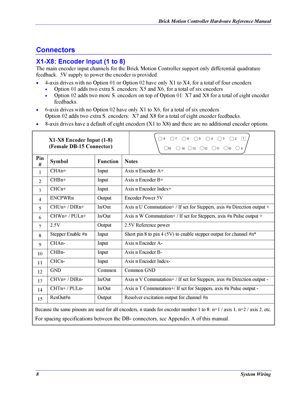
X1-X8: Encoder Input (1 to 8)
The main encoder input channels for the Brick Motion Controller support only differential quadrature feedback. 5V supply to power the encoder is provided.
•
•Option 01 adds two extra S. encoders: X5 and X6, for a total of six encoders
•Option 02 adds two more S. encoders on top of Option 01: X7 and X8 for a total of eight encoder feedbacks.
•
Option 02 adds two extra S. encoders: X7 and X8 for a total of eight encoder feedbacks.
•
8 | 7 |
| 6 | 5 | 4 | 3 | 2 | 1 |
| 15 | 14 | 13 | 12 | 11 | 10 |
| 9 |
| Pin | Symbol | Function | Notes | ||
| # | |||||
|
|
|
| |||
1 | CHAn+ | Input | Axis n Encoder A+ |
| ||
|
|
|
|
|
| |
2 | CHBn+ | Input | Axis n Encoder B+ | |||
|
|
|
|
|
| |
3 | CHCn+ | Input | Axis n Encoder Index+ | |||
|
|
|
|
|
| |
4 | ENCPWRn | Output | Encoder Power 5V | |||
|
|
|
|
|
| |
5 | CHUn+ / DIRn+ | In/Out | Axis n U Commutation+ / If set for Steppers, axis #n Direction output + | |||
|
|
|
|
|
| |
6 | CHWn+ / PULn+ | In/Out | Axis n W Commutation+ / If set for Steppers, axis #n Pulse output + | |||
|
|
|
|
|
| |
7 | 2.5V | Output | 2.5V Reference power | |||
|
|
|
|
|
| |
8 | Stepper Enable #n | Input | Short pin 8 to pin 4 (5V) to enable stepper output for channel #n* | |||
|
|
|
|
|
| |
9 | CHAn- | Input | Axis n Encoder A- | |||
|
|
|
|
|
| |
10 | CHBn- | Input | Axis n Encoder B- | |||
|
|
|
|
|
| |
11 | CHCn- | Input | Axis n Encoder Index- | |||
|
|
|
|
|
| |
12 | GND | Common | Common GND | |||
|
|
|
|
|
| |
13 | CHVn+ / DIRn- | In/Out | Axis n V Commutation+ / If set for Steppers, axis #n Direction output - | |||
|
|
|
|
|
| |
14 | CHTn+ / PULn- | In/Out | Axis n T Commutation+/ If set for Steppers, axis #n Pulse output - | |||
|
|
|
|
|
| |
15 | ResOut#n | Output | Resolver excitation output for channel #n | |||
|
|
|
|
|
| |
Because the same pinouts are used for all encoders, n stands for encoder number 1 to 8: n=1 / axis 1, n=2 / axis 2, etc. For spacing specifications between the DB- connectors, see Appendix A of this manual.
8 | System Wiring |