Brick Motion Controller Hardware Reference Manual
Setting up Quadrature Encoders
Digital quadrature encoders are the most common position sensors used with Geo Drives. Interface circuitry for these encoders comes standard on
Signal Format
Quadrature encoders provide two digital signals that are a function of the position of the encoder, each nominally with 50% duty cycle, and nominally
Typically, these signals are at 5V TTL/CMOS levels, whether
Differential encoder signals can enhance noise immunity by providing
Hardware Setup
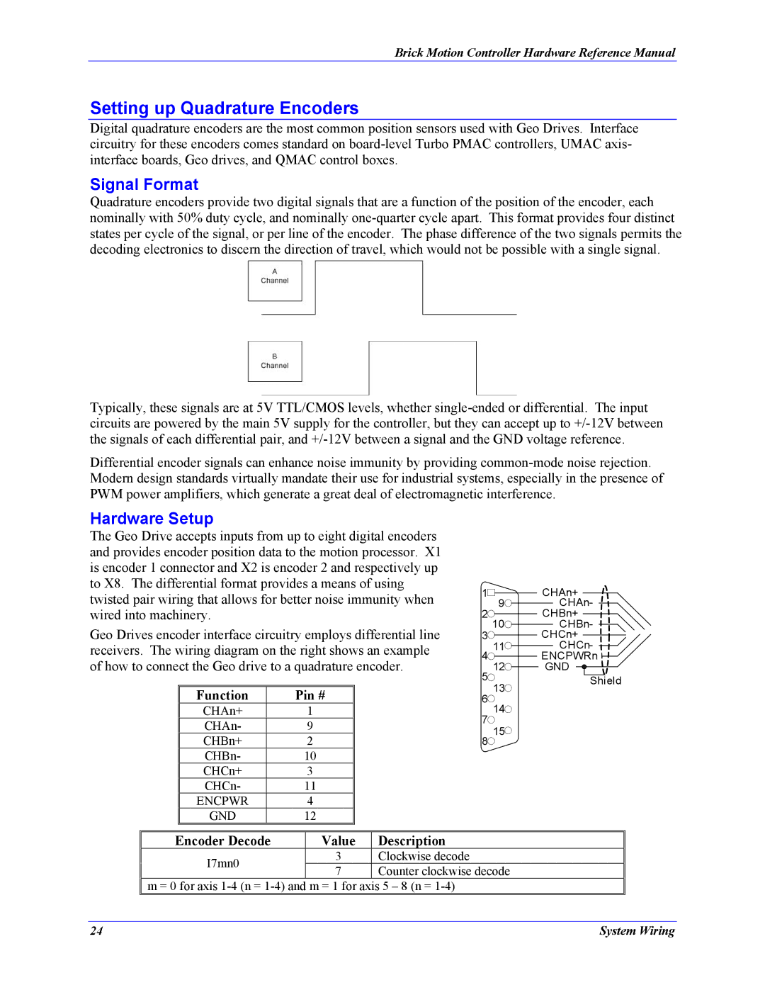
The Geo Drive accepts inputs from up to eight digital encoders and provides encoder position data to the motion processor. X1 is encoder 1 connector and X2 is encoder 2 and respectively up to X8. The differential format provides a means of using twisted pair wiring that allows for better noise immunity when wired into machinery.
Geo Drives encoder interface circuitry employs differential line receivers. The wiring diagram on the right shows an example of how to connect the Geo drive to a quadrature encoder.
Function | Pin # |
CHAn+ | 1 |
CHAn- | 9 |
CHBn+ | 2 |
CHBn- | 10 |
CHCn+ | 3 |
CHCn- | 11 |
ENCPWR | 4 |
GND | 12 |
1![]()
![]() CHAn+
CHAn+
9![]() CHAn-
CHAn-
2![]() CHBn+
CHBn+
10![]() CHBn-
CHBn-
3![]() CHCn+
CHCn+
11![]() CHCn-
CHCn-
4![]() ENCPWRn
ENCPWRn
12 | GND | |
5 | Shield | |
13 | ||
| ||
6 |
| |
14 |
| |
7 |
| |
15 |
| |
8 |
|
Encoder Decode | Value | Description | |
I7mn0 | 3 | Clockwise decode | |
7 | Counter clockwise decode | ||
|
m = 0 for axis
24 | System Wiring |