Operating manual
Software version
Page
Preface
ACCUMULATOR AND BATTERY OPERATION
Contents
SAFETY INSTRUCTIONS
PREFACE
Entering and transmitting a DiSEqC command
Contents
Transmitting and receiving a DiSEqC command TX + RX
Installation of a UFOµ unit EXU 544 in conjunction with the MSK
TV OPERATION
Contents
DIGITAL MEASUREMENTS
IF RP DIGITAL MENU
Contents
RETURN PATH IF MENU
RADIO OPERATION
SCREEN MENU
Contents
SETTING MENU
SYSTEM MENU
CONST MENU
Contents
SPECTRUM MENU
DVB-T
INTERFACES
Contents
MAINTENANCE, STORAGE AND CUSTOMER SERVICE
TECHNICAL APPENDIX
DOWNLOADING NEW MSK33 OPERATING SOFTWARE
Contents
TECHNICAL DATA
Important Notes
General safety information
Explanation of symbols
Validity of this manual
Proper use
Safety Instructions
Connections
Mechanical loadbearing capacity
Functions
Functions
Function
Functions overview
Functions
Return path LP
6 On/Off switch Standby
Displays, Operating Elements and Connections
Front panel
1 TFT display screen 3 Numerical entry field
Displays, Operating Elements and Connections
Rear panel
1 Mains connection 3 Mains switch 5 DC socket Option / XLR-socket
7 Headphone connection
MSK 33 front viel
Observing angle of the on screen display
Displays, Operating Elements and Connections
The angle of view from the side to the TFT display is +
Frequently recurring softkeys
Operating Concept
The screen
Softkeys
The main menu
General information for operation
Menu selection
Operating Concept
On/Off switch
Place of installation of the MSK
Mains voltage / mains switch
Safety fuse
DC socket option
Accumulator and Battery Operation
Accumulator operation
Only use the supplied cables with the original connectors
Headphone connection
Connections
RF output
Modem / RS232 interface
Maximal input level
Measurement Possibilities
Level measurement
Number of the fed
BACK
Sat Operation
Sat menu
sat frq LNB CONTROL analog digit DVBS SAT MEASURE
BACK 22kHz off 14.0V on 18.0V off 09750 Lo DiSEqC VSEC
Setting of the LNB voltage supply
LNB U= 14,0V I=181mA
BACK sat frq LNB CONTROL digit DVBS analog SAT MEASURE
Sat Operation
SCAN
Switch-over of ANALOG digit. DVBS
Bargraph
22kHz
22 kHz control signal
LNB control menu
14.0V
DiSEqC
Checking the LNB supply voltage of a satellite receiver
Calling up the DiSEqC/V SEC menu
Sat Operation
DiSEqC menu
Transmitting and receiving a DiSEqC command TX + RX
Sending a DiSEqC command TX
RX assessment
Display field A
Submenu for entering DiSEqC commands
TX display field
Display field B
Example Entering and transmitting a DiSEqC command
Simple DiSEqC
data burst tone burst tx
Sat Operation
Display fields
UFOmicro DiSEqC menu
General information
FRAME ADD COM
DATA
rx tx+rx Command
FRAME
TX E2
Installation of a UFOµ unit EXU 544 in conjunction with the MSK
Sat Operation
VSEC
Sending a V-SEC command TX
V-SEC menu
TX- BB
SUBCAR
Level-dependent acoustic signal
Initial ANALOG-menu
level
Selecting the video hub
Second ANLAOG menu
Selecting the colour standards PAL, SECAM and NTSC
Video polarity
Sat subcarrier menu
Audio carrier setting
Setting of the de-emphasis
Selecting the subcarrier recep
Audio carrier table for reception type
Audio carrier tables for the satellite reception
Sat Operation
Audio carrier table for reception type
SAT DIGITAL menu
Symbol rate entry
Digital Measurements
MPEG
Level measurement DIGITAL Min./Max. levels
Digital Measurements
analog
TV Operation
TV menu
digit
LNB U= 0.0 V I= 0 mA
TV control menu
TV-DiSEqC /VSEC menu
LNB supply voltage
Audio carrier table for TV reception
Analogue menu
Selecting the standard
Selecting the audio carriers
Measuring the min./max. level
TV MEASURE ALL SC1/SC2-13.5/-19.5dB
NICAM -18.5 dB BER 5.6E-06
Measuring the current level
mode
TV DIGITAL menu
QAM64
TV MEASURE ALL
C21 474.00MHz
chBW
8 MHz
DVB-T optional
IF CONTROL analog
Return Path IF Menu
Return path IF menu
IF MEASURE
Level-dependent acoustic signal
ANALOG menu
Audio carrier table for IF reception
Return Path IF Menu
Return Path IF Menu
Measurement of the min./max. level
Measurement of the Nicam audio carrier spacing and the bit error rate
TV MEASURE ALL SC1/SC2-13.5/-19.5dB
RP 48.25MHz
Entering symbol rate
IF RP DIGITAL Menu
RP MEASURE ALL
RADIO menu
Level-dependant acoustic signal
Radio Operation
RADIO ANALOG menu
Radio Operation
FM MEASURE ALL min/max 61.5/64.5dBµV
Measuring the min/max level
Measuring the current level
CVBS
AV Menu
CVBS
Decoder operation
LVDS LVDS
Fb RGB off Fb RGB on
LVDS
Breaking voltage
Norm dig. television Statusrunning CAno
MPEG Decoder Menu Optional
PAT 08 ZDF
show
Screen menu
Setting Menu
Modem menu
Measuring unit
Setting the colour saturation
Setting the brightness
Setting the contrast
Setting the background light
Setting the time Click button
click off fact. setup serv
Setting the date
System Menu
Saving the unit settings
Saving and calling up unit settings
Copy Menu
Calling up saved settings
Date and time Channel number, frequency Analogue measurement A, level
Audio carrier spacing NICAM - 20 dB Bit error rate NICAM 8.20E
Copy Menu
Printing out all measurements in TV mode
AUTO MEASURE TRACK MVG10
Mode Menu
SPECTR
CONST
Holding the videotext page
Text Menu
Enlarging the videotext page
Original videotext size
Scope Menu
Horizontal zoom -Enlarging the video signal
Horizontal zoom - Reducing the video signal
audio DiSEqC
rflev +0dB sample
Measurement of the amplitude of the video signal
Measurement of video signals via the AV socket SCART
Selecting the video line
Audio Scope
Position of the audio signal
Measuring an audio signal via the AV socket SCART
Increasing time / unit
Saving function
Position and triggering of the DiSEqC signal
DiSEqC Scope
shot cont
Spectral Menu
Level measurement of analogue signals
Level measurement of digital signals
marker
ANALOG marker
C/N measurement of analogue signals in Sat operation
Selecting the spectrum representation
marker ana
zoom marker
C/N measurement of digital signals in Sat operation
Cross-polarisation measurement on signals in SAT operation
max off
Const Menu
Constellation diagram for QPSK DVB-S
Measurement of the bit error rate BER
Colour representation of I/Q value pairs
Carrier offset
Measurement of signal noise ratio SNR
QPSK no
Frontend locked
27.500 SR 3/4 CR
Selecting the symbol rate symbol-clock
Inverting /not inverting a constellation diagram
Mode QPSK
QPSK signal with phase noise LNC
Examples for QPSK constellation diagrams
QPSK signal without faults
QPSK signal with intermodulation noise
Measurement of the bit error rate BER
Constellation diagram for QAM DVB-C
Measurement of modulation error rate MER
Const Menu
Selecting the symbol rate symbol-clock
Inverting /not inverting constellation diagram
Zoom
BER = Bit error rate 1.7 e-06 MER = Modulation error rate 29.5 dB
Examples for QAM constellation diagram
Const Menu
64 QAM signal with amplitude hum of an amplifier
64 QAM Signal with phase noise of a converter
64 QAM signal with I/Q phase error of a converter
64 QAM signal with signal I/Q amplitude error of the converter
Measurement of signal noise ration SNR
Constellation diagram DVB-T optional
Measurement of bit error rate BER
DVB-T
Hierarchy
DVB-T
Code rate Guard Invers Frontend locked Channel display
DVB-T
Impulse response representation Echo representation optional
DVB-T
MVG10
Broadband Cable Analysis Measuring System MSK MVG
Measuring principle
MSK33
in MVG 10 tracking mode with the second softkey
Broadband Cable Analysis Measuring System MSK MVG
max off
Downstream measurement
Comfortable upstream 4.0…80 MHz and Downstream 47…860 MHz measurement
Upstream measurement
Broadband Cable Analysis Measuring System MSK MVG
Retransmission of the spectrum received by the MSK 33 1 with a MVG
Auto Measure
list rcl. ---setting
NO SETTINGS
point
Connection cable for modem / RS
Interfaces
Modem / RS 232 interface
Setting hardware handshake
Setting baud rate
Setting local echo
rate
Operating of the MSK 33 via modem
Code Password
The log-in procedure
The TTY mode
Example for logging-in in ANSI mode
Requesting help
Interfaces
Interfaces
Example Entry of the LNB oscilla- tor frequency
Switch-over of the operating type of the MSK
List of the command abbreviations
General commands
settings of the MSK
Interfaces
Loading and saving predefined settings
Loading the setting by the
Function testing
Maintenance, Storage and Customer Service
Maintenance
Customer service
Before opening the unit, disconnect the supply voltage ge
Printer paper-exchanging the ribbon
Maintenance, Storage and Customer Service
Ribbon exchange
Command overview address byte
Overview of DiSEqC commands
Command overview framing byte
Technical Appendix
Switch
Command overview command byte
Command
Reads switching status flags committed port
Command for Kathrein matrix 9xx-series
DiSEqC commands for Kathrein matrices
Command overview data byte
Command for Kathrein matrix EXR
Technical Appendix
Channel tables
Channel and frequency table standard B/G frequency in MHz
Channel and frequency table standard Lfrequency in MHz
Technical Appendix
Channel and frequency table standard D/K frequency in MHz
Technical Appendix
Channel and frequency table standard I frequency in MHz
Technical Appendix
Channel and frequency table standard M/N frequency in MHz
Technical Appendix
Channel and frequency table standard M/Nfrequency in MHz
Technical Appendix
Power supply
Technical Data
Technical data
Technical Data
Assignment of the SCART socket
Accessories
Scope of delivery
Technical Data
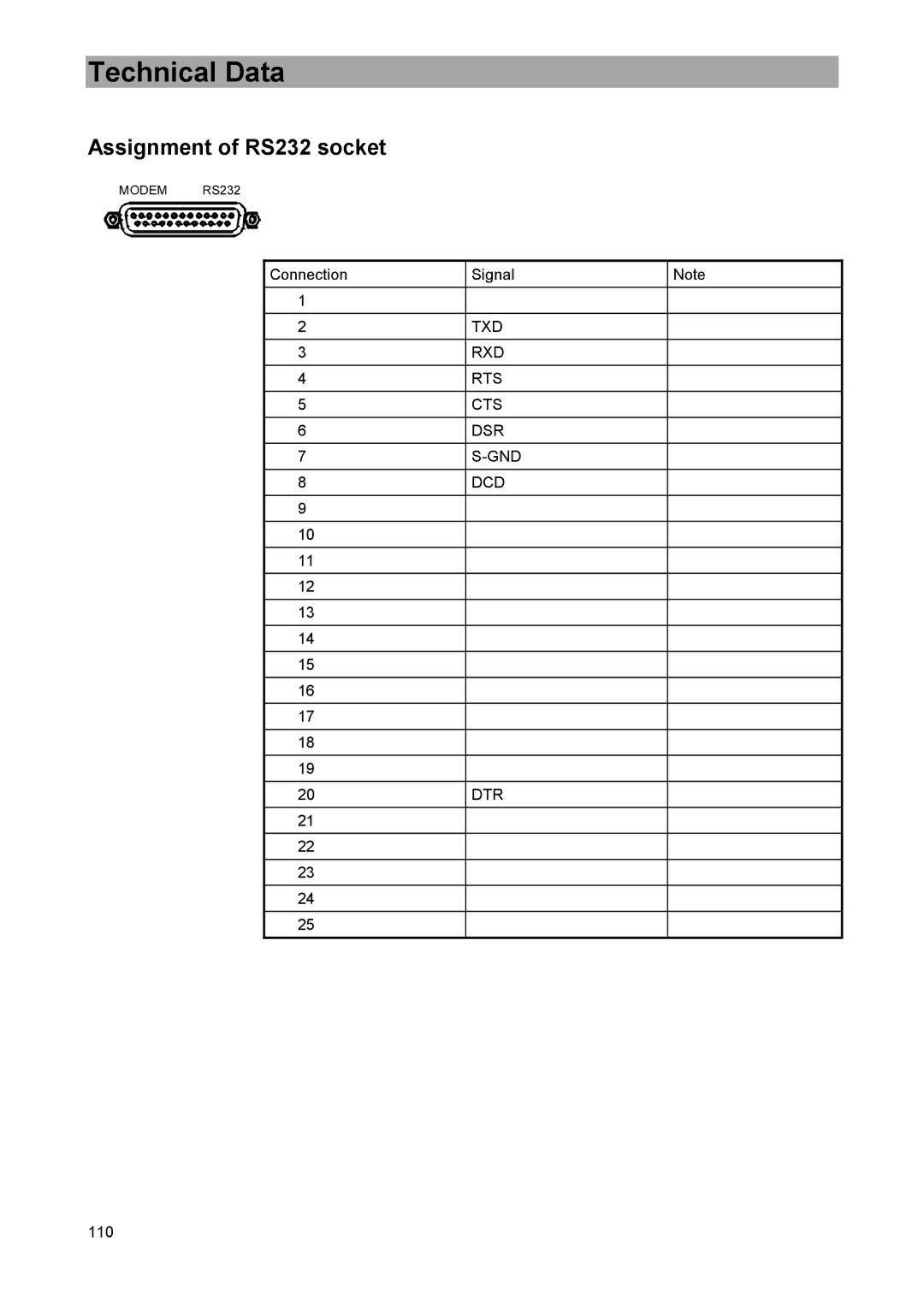
Assignment of RS232 socket
Technical Data
TS PARALLEL
Assignment of socket TS PARALLEL optional
Technical Data
MSK 33/Q
Unit variants
MSK 33/G
MSK 33/M
SETTING / SYSTEM
Downloading New MSK33 Operating Software
General notes
9986498/0206 ZWT Subject to alterations