Displays, Operating Elements and Connections
Front panel
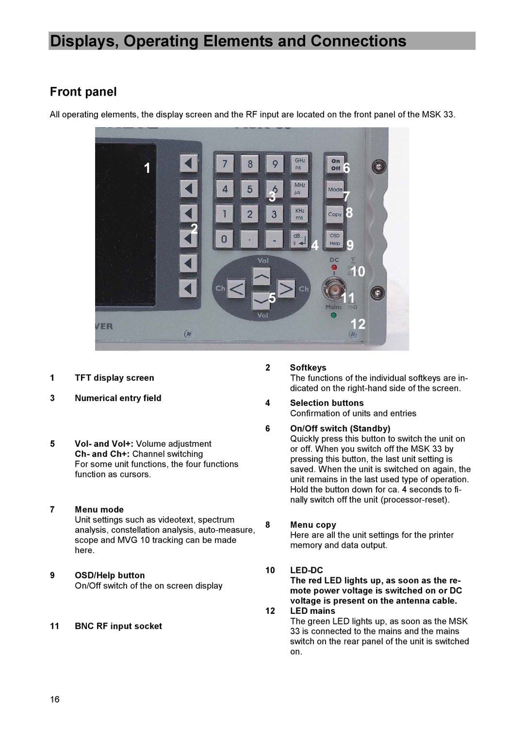
All operating elements, the display screen and the RF input are located on the front panel of the MSK 33.
1 | 6 |
3 | 7 |
2 | 8 |
| |
4 | 9 |
10
5 11
12
1TFT display screen
3Numerical entry field
5Vol- and Vol+: Volume adjustment
Ch- and Ch+: Channel switching
For some unit functions, the four functions function as cursors.
7Menu mode
Unit settings such as videotext, spectrum analysis, constellation analysis,
9OSD/Help button
On/Off switch of the on screen display
11 BNC RF input socket
2Softkeys
The functions of the individual softkeys are in- dicated on the
4Selection buttons Confirmation of units and entries
6On/Off switch (Standby)
Quickly press this button to switch the unit on or off. When you switch off the MSK 33 by pressing this button, the last unit setting is saved. When the unit is switched on again, the unit remains in the last used type of operation. Hold the button down for ca. 4 seconds to fi- nally switch off the unit
8Menu copy
Here are all the unit settings for the printer memory and data output.
10LED-DC
The red LED lights up, as soon as the re- mote power voltage is switched on or DC
voltage is present on the antenna cable.
12LED mains
The green LED lights up, as soon as the MSK 33 is connected to the mains and the mains switch on the rear panel of the unit is switched on.
16