Technical Appendix
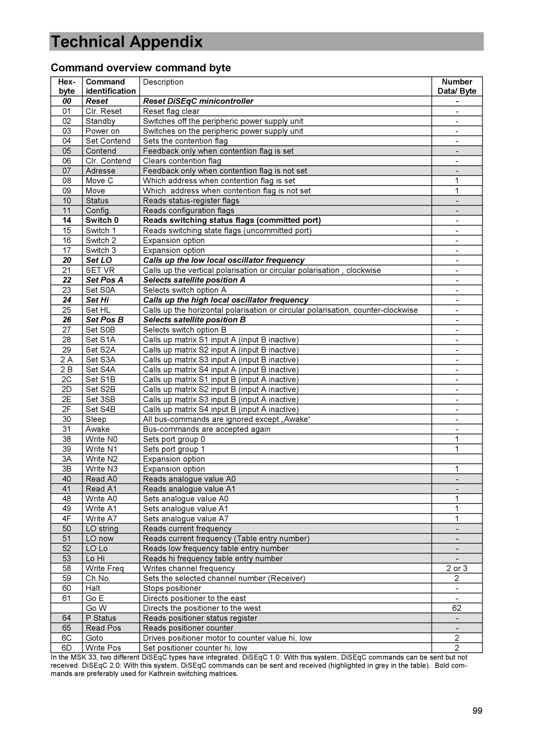
Command overview command byte
Hex- | Command | Description | Number |
byte | identification |
| Data/ Byte |
00 | Reset | Reset DiSEqC minicontroller | - |
01 | Clr. Reset | Reset flag clear | - |
02 | Standby | Switches off the peripheric power supply unit | - |
03 | Power on | Switches on the peripheric power supply unit | - |
04 | Set Contend | Sets the contention flag | - |
05 | Contend | Feedback only when contention flag is set | - |
06 | Clr. Contend | Clears contention flag | - |
07 | Adresse | Feedback only when contention flag is not set | - |
08 | Move C | Which address when contention flag is set | 1 |
09 | Move | Which address when contention flag is not set | 1 |
10 | Status | Reads | - |
11 | Config. | Reads configuration flags | - |
14 | Switch 0 | Reads switching status flags (committed port) | - |
15 | Switch 1 | Reads switching state flags (uncommitted port) | - |
16 | Switch 2 | Expansion option | - |
17 | Switch 3 | Expansion option | - |
20 | Set LO | Calls up the low local oscillator frequency | - |
21 | SET VR | Calls up the vertical polarisation or circular polarisation , clockwise | - |
22 | Set Pos A | Selects satellite position A | - |
23 | Set S0A | Selects switch option A | - |
24 | Set Hi | Calls up the high local oscillator frequency | - |
25 | Set HL | Calls up the horizontal polarisation or circular polarisation, | - |
26 | Set Pos B | Selects satellite position B | - |
27 | Set S0B | Selects switch option B | - |
28 | Set S1A | Calls up matrix S1 input A (input B inactive) | - |
29 | Set S2A | Calls up matrix S2 input A (input B inactive) | - |
2 A | Set S3A | Calls up matrix S3 input A (input B inactive) | - |
2 B | Set S4A | Calls up matrix S4 input A (input B inactive) | - |
2C | Set S1B | Calls up matrix S1 input B (input A inactive) | - |
2D | Set S2B | Calls up matrix S2 input B (input A inactive) | - |
2E | Set 3SB | Calls up matrix S3 input B (input A inactive) | - |
2F | Set S4B | Calls up matrix S4 input B (input A inactive) | - |
30 | Sleep | All | - |
31 | Awake | - | |
38 | Write N0 | Sets port group 0 | 1 |
39 | Write N1 | Sets port group 1 | 1 |
3A | Write N2 | Expansion option |
|
3B | Write N3 | Expansion option | 1 |
40 | Read A0 | Reads analogue value A0 | - |
41 | Read A1 | Reads analogue value A1 | - |
48 | Write A0 | Sets analogue value A0 | 1 |
49 | Write A1 | Sets analogue value A1 | 1 |
4F | Write A7 | Sets analogue value A7 | 1 |
50 | LO string | Reads current frequency | - |
51 | LO now | Reads current frequency (Table entry number) | - |
52 | LO Lo | Reads low frequency table entry number | - |
53 | Lo Hi | Reads hi frequency table entry number | - |
58 | Write Freq | Writes channel frequency | 2 or 3 |
59 | Ch.No. | Sets the selected channel number (Receiver) | 2 |
60 | Halt | Stops positioner | - |
61 | Go E | Directs positioner to the east | - |
| Go W | Directs the positioner to the west | 62 |
64 | P Status | Reads positioner status register | - |
65 | Read Pos | Reads positioner counter | - |
6C | Goto | Drives positioner motor to counter value hi, low | 2 |
6D | Write Pos | Set positioner counter hi, low | 2 |
In the MSK 33, two different DiSEqC types have integrated. DiSEqC 1.0: With this system, DiSEqC commands can be sent but not
received. DiSEqC 2.0: With this system, DiSEqC commands can be sent and received (highlighted in grey in the table). Bold com- mands are preferably used for Kathrein switching matrices.
99
