|
|
| UPS Alarm and Status Messages | |
|
|
|
| |
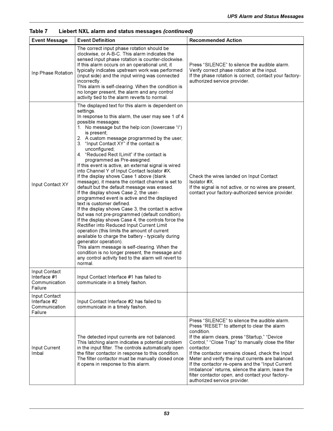
Table 7 | Liebert NXL alarm and status messages (continued) | |||
|
|
| ||
Event Message | Event Definition | Recommended Action | ||
|
| The correct input phase rotation should be |
| |
|
| clockwise, or |
| |
|
| sensed input phase rotation is | Press “SILENCE” to silence the audible alarm. | |
|
| If this alarm occurs on an operational unit, it | ||
Inp Phase Rotation | typically indicates upstream work was performed | Verify correct phase rotation at the input. | ||
(input side) and the input wiring was connected | If the phase rotation is correct, contact your factory- | |||
|
| incorrectly. | authorized service provider. | |
|
| This alarm is |
| |
|
| no longer present, the alarm and any control |
| |
|
| activity tied to the alarm reverts to normal. |
| |
|
| The displayed text for this alarm is dependent on |
| |
|
| settings. |
| |
|
| In response to this alarm, the user may see 1 of 4 |
| |
|
| possible messages: |
| |
|
| 1. No message but the help icon (lowercase “i“) |
| |
|
| is present; |
| |
|
| 2. A custom message programmed by the user; |
| |
|
| 3. “Input Contact XY” if the contact is |
| |
|
| unconfigured; |
| |
|
| 4. “Reduced Rect ILimit” if the contact is |
| |
|
| programmed as |
| |
|
| If this event is active, an external signal is wired |
| |
|
| into Channel Y of Input Contact Isolator #X. | Check the wires landed on Input Contact | |
|
| If the display shows Case 1 above (blank | ||
Input Contact XY | message), it means the contact channel is set to | Isolator #X. | ||
default but the default message was erased. | If the signal is not active, or no wires are present, | |||
|
| |||
|
| If the display shows Case 2, the user- | contact your | |
|
| programmed event is active and the displayed |
| |
|
| text is customer defined. |
| |
|
| If the display shows Case 3, the contact is active |
| |
|
| but was not |
| |
|
| If the display shows Case 4, the controls force the |
| |
|
| Rectifier into Reduced Input Current Limit |
| |
|
| operation (this limits the amount of current |
| |
|
| available to charge the battery - typically during |
| |
|
| generator operation). |
| |
|
| This alarm message is |
| |
|
| condition is no longer present, the message and |
| |
|
| any control activity tied to the alarm will revert to |
| |
|
| normal. |
| |
Input Contact | Input Contact Interface #1 has failed to |
| ||
Interface #1 |
|
| ||
Communication | communicate in a timely fashon. |
| ||
Failure |
|
|
| |
Input Contact | Input Contact Interface #2 has failed to |
| ||
Interface #2 |
|
| ||
Communication | communicate in a timely fashon. |
| ||
Failure |
|
|
| |
|
|
| Press “SILENCE” to silence the audible alarm. | |
|
|
| Press “RESET” to attempt to clear the alarm | |
|
|
| condition. | |
|
| The detected input currents are not balanced. | If the alarm clears, press “Startup,” “Device | |
|
| This latching alarm indicates a potential problem | Control,” “Close Trap” to manually close the filter | |
Input Current | in the input filter. The controls automatically open | contactor. | ||
Imbal |
| the filter contactor in response to this condition. | If the contactor remains closed, check the Input | |
|
| The filter contactor must be manually closed once | Meter and verify the input currents are balanced. | |
|
| it opens in response to this alarm. | If the contactor | |
|
|
| Imbalance” returns, silence the alarm, leave the | |
|
|
| filter contactor open, and contact your factory- | |
|
|
| authorized service provider. | |
53
