Installation
NOTE: The use of a flexible coupling is required between the encoder and the motor shaft.
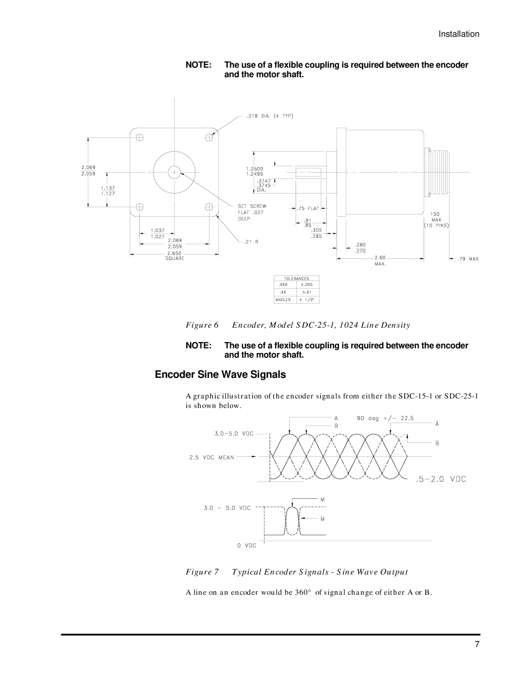
Figure 6 Encoder, Model SDC-25-1, 1024 Line Density
NOTE: The use of a flexible coupling is required between the encoder and the motor shaft.
Encoder Sine Wave Signals
A graphic illustration of the encoder signals from either the
Figure 7 Typical Encoder Signals - Sine Wave Output
A line on an encoder would be 360° of signal change of either A or B.
7