Installation
Shield
Two shield terminals are provided as a connection point for cable shields. These two terminals are connected internally to the input power ground terminal on the unit. Shields should be connected on one end only, preferably at the 525 PMC.
Command (+) and Command (-) Output
Command (+) and Command
NOTE: It is important that the control ground on the amplifier is connected to the input power ground on the 525 PMC.
Command Output Polarity
A positive voltage out of the command output must cause a clockwise rotation of the motor shaft as viewed from the shaft end. The encoder should turn clockwise as viewed from the shaft. This will ensure a positive count within the 525 PMC.
Signal Path
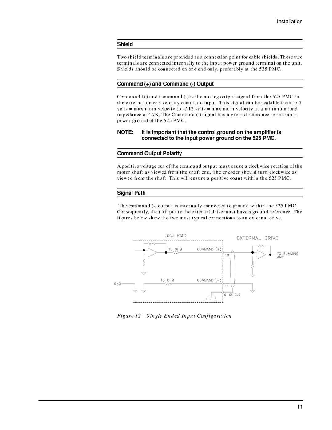
The command
Figure 12 Single Ended Input Configuration
11