525 Programmable Motion Controller
Minimum System Configuration
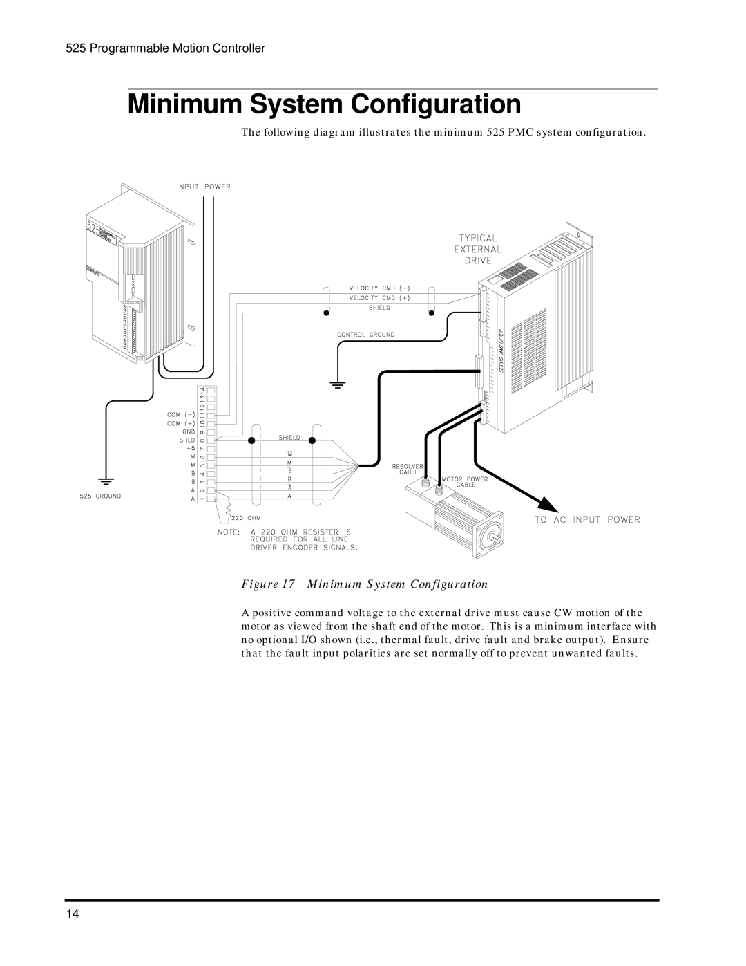
The following diagram illustrates the minimum 525 PMC system configuration.
Figure 17 Minimum System Configuration
A positive command voltage to the external drive must cause CW motion of the motor as viewed from the shaft end of the motor. This is a minimum interface with no optional I/O shown (i.e., thermal fault, drive fault and brake output). Ensure that the fault input polarities are set normally off to prevent unwanted faults.
14
