525 Programmable Motion Controller
In 525's, the signal terminator capacitance is approximately 1000pf and a typical cable capacitance runs about 30pf/ft. Therefore, the cable length should be limited to 50 feet. Longer serial interface cables are not recommended.
In
It is very important that the serial cables are not altered in the field. It is also important to follow any recommendations given in the product manuals on how to connect or terminate these cables.
NOTE: As a general rule, the minimum cable bend radius is ten times the cable outer diameter.
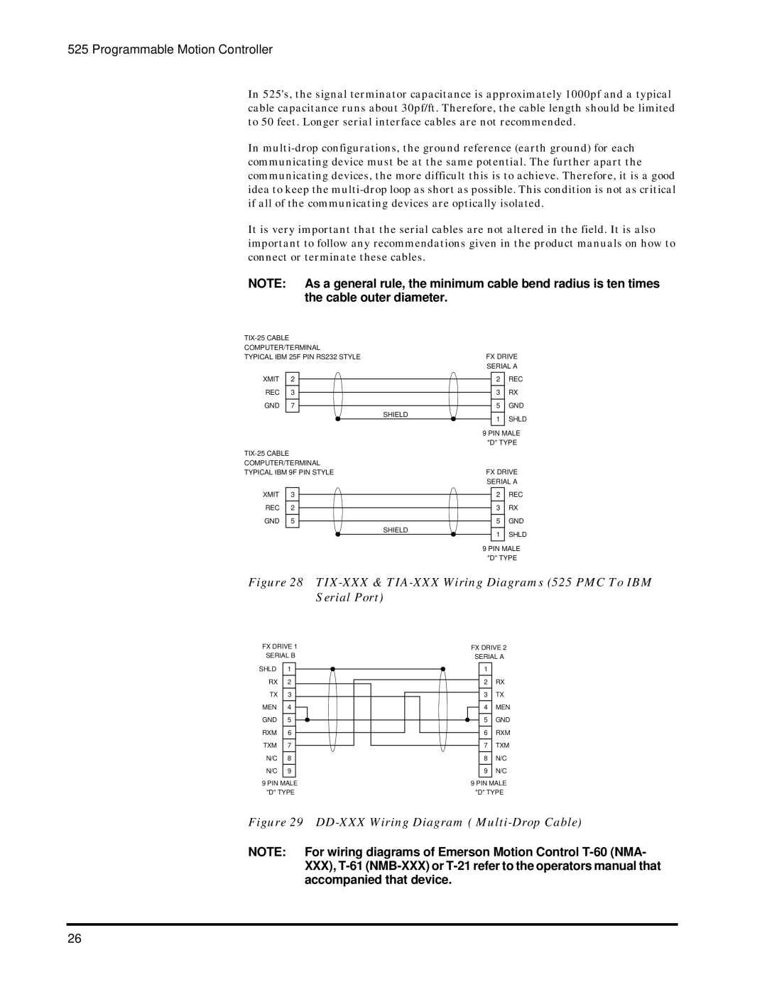
COMPUTER/TERMINAL
TYPICAL IBM 25F PIN RS232 STYLEFX DRIVE
SERIAL A
XMIT 2
REC 3
GND 7
SHIELD |
2REC
3RX
5GND
1SHLD
9 PIN MALE "D" TYPE
FX DRIVE SERIAL A
XMIT 3
REC 2
GND 5
SHIELD |
2REC
3RX
5GND
1SHLD
9 PIN MALE "D" TYPE
Figure 28 TIX-XXX & TIA-XXX Wiring Diagrams (525 PMC To IBM Serial Port)
FX DRIVE 1 SERIAL B
SHLD | 1 |
RX | 2 |
TX | 3 |
MEN | 4 |
GND | 5 |
RXM | 6 |
TXM | 7 |
N/C | 8 |
N/C | 9 |
9 PIN MALE "D" TYPE
FX DRIVE 2 SERIAL A
1 |
|
2 | RX |
3 | TX |
4 | MEN |
5 | GND |
6 | RXM |
7 | TXM |
8 | N/C |
9 | N/C |
9 PIN MALE "D" TYPE
Figure 29 DD-XXX Wiring Diagram ( Multi-Drop Cable)
NOTE: For wiring diagrams of Emerson Motion Control
26