Manuals
/
Emerson
/
Photography
/
Photo Scanner
Emerson
54e pH/ORP
instruction manual
Wiring to Model
Models:
54e pH/ORP
1
19
84
84
Download
84 pages
55.69 Kb
16
17
18
19
20
21
22
23
Troubleshooting
Specs
Install
Controller Mode Priority Chart
Changing Alarm Setpoints
Password
Fault 22.00 mA
Interval timer
Section Wiring
Warranty
Page 19
Image 19
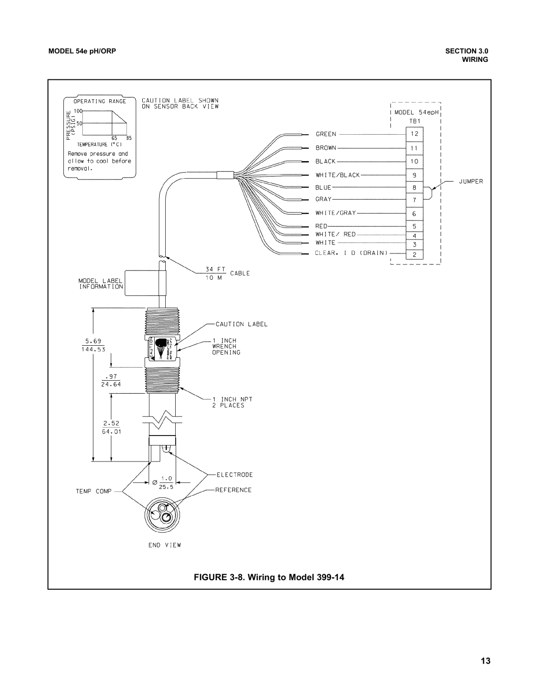
MODEL 54e pH/ORP
SECTION 3.0
WIRING
FIGURE
3-8.
Wiring to Model
399-14
13
Page 18
Page 20
Page 19
Image 19
Page 18
Page 20
Contents
Model 54e pH/ORP
PH/ORP Hart Analyzer/Controller
Electrical Shock Hazard
Essential Instructions
Page
Model 54E PH/ORP Microprocessor Analyzer
Description and Specifications
Section Title
List of Tables
Appendix Title
Table No Title
About This Document
Table of Contents List of Figures
General Description
Section Description and Specifications
Description of Controls
Current Outputs
Specifications Physical Specifications General
Power
Relative Humidity 95%, non condensing Alarms
Recommended Sensors
Analyzer Specifications @ 25C
Code Options
Ordering Information
Part NO. Description
Unpacking and Inspection
Section Installation
Mechanical Installation
Locating the Controller
Panel Mounting
Alarm Relay Output Wiring
Section Wiring
Power Input Wiring
Analog Output Wiring
454EPH02
PH Sensor Compatibility
PH Sensor Wiring
Tions will Result in Controller MALFUNC- Tion
454EPH01
Cable Dressing
Final Electrical Check
Wiring to Model
Introduction
Section Calibration
Adjust temp 25.1 C
Hold Mode Off
Temperature Calibration
Buffer 1 -- Wait
Autocal buffer
Automatic TWO-POINT Calibration
Use the arrow keys to select the correct buffer
Auto buffer cal done
Calibration Notes
Manual TWO-POINT Calibration
Calibrate point
Pt 04.00pH 25C
Pt calibration done
SINGLE-POINT pH Calibration
Standardize 7.01 pH
59.16 mV/pH
Temperature Compensation Options
Temp comp Auto
Output trim
Output trim
Hold Mode
Trim Outputs
PH Settings List
Section Software Configuration
Ranges Factory Settings User Settings
Diagnostics Section
Outline of Menu Levels
Setpoint 07.00 pH
Alarm High 14.00pH
Changing Alarm Setpoints
Simulate tests
Changing Output Setpoints PID only
Setpoint 7.00 pH
4mA 0.00 pH 20mA 2.00 pH
Setpoint + 06.90 pH
MA +00.00 pH
Output
Output
MA 0.00 pH 20 mA 14.00 pH Output 1 12.00 mA
Simulated tests
Alarm setpoints Output setpoints
Test output Test alarm
Testing Outputs and Alarms
Test alarm 1 Open
Test alarm 1 Open
Measure pH
Display right AL2
Security Caution
Display contrast Timeout On
Output Control Parameters
Control Mode
Display
Changing Output Parameters
Range 4-20 mAl
Fault 22.00 mA
Range 4-20 mA
Hold Disable feature
Fault 22.00mA
Output 2 control Output 2 setup
Hold feature setup
Alarm 3 control
Alarms
Interval timer
Relay Default None
Alarm Low
Setpoint 0.01 pH Delay 0 sec
Hysteresis 0.01 pH Delay 0 sec
URV 2.00 pH
Relay default None
Setpoint +07.00 pH
Time period 30 sec
Alarm 4 Setup
Alarm Fault
Feed limit Disable
Timeout 3600 sec
Recovery 600 sec
Timer Disable
On time 120 sec
Interval Timer Examples
Diagnostics Off
Diagnostics
Zero offset 60 mV
Stabilize pH 0.01 pH Stabilize time 10 sec
Diagnostics
Auto Calibration Setup
Autocal Standard
Standard Buffers
Auto Calibration Setup
Section Theory of Operation
Continuous Sensor Diagnostics
Typical set points
Interval Timer
See .8 for instructions on chang- ing these setpoints
Time Proportional Control TPC Mode Code
Alarm Relays
Analog Outputs
Normal Mode
Action Definitions
Controller Mode Priority
Controller Mode Priority Chart
Condition Definitions
Measurement and Set Point Feedback Control
PID Control Mode Combinations
PID Control Code
PID Control
Proportional Gain Plus Integral Reset
Proportional Mode Gain
Control Loop Adjustment and Tuning
Process Reaction Curve
Process Reaction Curve Method
PID Control
Password Protection
Section Special Procedures and Features
Level 1 3 Password Privileges
Lock all
Configuring Security
Security
Custom Curve
Temp coeff +.000
Solution Temperature Compensation
Sensor iso 07.00 pH
Operate iso +07.00 pH
Troubleshooting is easy as 1, 2, 3…
Section Troubleshooting
Diagnostic Messages Description of problem
Diagnostic Messages
Symptom Action
Quick Troubleshooting Guide
Diagnostic Variables
Theoretical pH vs. Millivolt Values at 25C 77F
Ohms Ambient Temperature
Troubleshooting Guidelines
Temperature Compensation Circuit
Troubleshooting Procedure
Preamp in a junction box Figure
Preamplifier Troubleshooting Procedure
Controller preamp check Figure
Junction Box Preamplifier Check
No Power
Troubleshooting Guide
Coated glass electrode Clean with soft cloth and clean water
Password protected
Part Number Description
Replacement Parts
General
Warranty Repair
NON-WARRANTY Repair
Section Return of Material
Quick Startup ORP
Appendix a ORP Configuration
Item Choices ORP Settings User Settings
Table A-1. ORP Settings List
Diagnostics Section
Choices ORP Settings User Settings
Simulated tests
Output setpoints
ORP Calibration
Standardize 400 mV
Sensor or Circuit Board only
Return of Materials Request
Return of Material
Warranty
Specifications subject to change without notice
Top
Page
Image
Contents